John Deere 4300 complete rebuild

   / John Deere 4300 complete rebuild #151  
Dave, I really appreciate your taking the time to snap pictures and post. I know how annoying it can be to take a pic with greasy fingers...

Anyhow, I'm sitting on the edge of my chair with baited breath waiting for the next update. Are you going to tear into the Eaton HST unit?
 
   / John Deere 4300 complete rebuild
  • Thread Starter
#152  
First a little more in the HST control, then I will open up the HST.

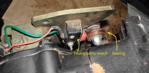
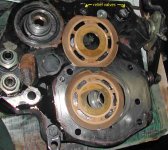
The first photo shows the back of the swash plate control plate, where
the neutral safety switch is located. This switch has been replaced...and
it was done incorrectly. The wires are supposed to be routed thru a hole in
the control plate; I am sure this would reduce the fatigue on the wires.
These switches will fail eventually, and it is very hard to get at with the
tractor all together. The mechanic struggled to bolt the new switch in, and
you can see that he put one bolt in such that it protruded into the path of
control tie rod. The other bolt was too long and it looks like it is touching
the HST pump housing. When the bearing starts to go, the switch will
fail to work.

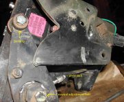
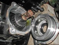
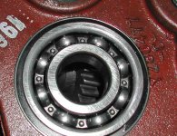
In the second photo, I have pointed out the critical sealed bearing that
rides in the V-groove of the swashplate control plate. These go bad, too,
but are cheap and not too hard to replace. This bearing, or failure to
adequately grease the control plate pivot (note the long zerk) are very
common causes of HST pedals failing to spring back to neutral. All the
tractor HSTs I have seen use a neutral adjustment bolt arrangement like
this to adjust for no movement in neutral. Since I will remove and clean
the pivot, I will have to reset the neutral.

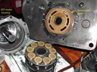
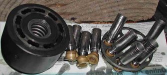
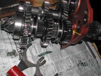
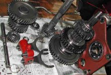
Next, I have removed the HST motor, which is also known as a fixed
displacement hydraulic piston motor. You can see the main elements....it
is really not too complicated in there. In this motor the swash plate has
a fixed angle, so the displacement is fixed. The HST pump has a variable
displacement, by virtue of the fact that you can vary the swash plate
angle. I will show that later.

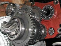
Inside the housing of the motor, you can see the swash plate, upon which
the slipper end of the pistons ride. The pistons are pushed out of the
block by oil pressure from the pump, and they act upon the angled swash
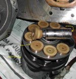
plate. This imparts rotary motion to the shaft. There is a large hole in the
end of the slipper so that some of the oil under pressure can squeeze out
and allow the slipper to ride on a thin film of oil. Look closely and you will
see scratches in the slippers....those are put there intentionally to help
spread the oil film.

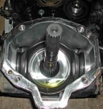
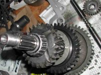
The other end of the cylinder block acts, under spring pressure, upon the
valve plate, which seems to be composed of a copper/steel laminate. The
plate has some wear, but I do not think I need to replace them. This wear
may be due to towing the dead tractor in gear. Otherwise the needle
bearings and ball bearings are all good, and there is no scoring on the slippers
or swash plate.

If the tractor had been operated with dirty oil or very low oil, it is likely that
you would see a scored swash plate and damaged slippers.
 

Attachments

  • HST_5.JPG
    HST_5.JPG
    44.6 KB · Views: 767
  • HST_6.JPG
    HST_6.JPG
    66.4 KB · Views: 828
  • HST_7.JPG
    HST_7.JPG
    74.4 KB · Views: 819
  • HST_8.JPG
    HST_8.JPG
    87.8 KB · Views: 989
   / John Deere 4300 complete rebuild
  • Thread Starter
#153  
Dave, in that third pic on your last post, you show the inside of the tunnel. Any idea what the hyd/trans fluid level would be in a normally full condition? Mostly just curious as to how much gets submerged in there.

Based on the position of the hyd oil sight glass on the rear of the PTO
cover plate, the tunnel is somewhere around half full when the oil is at the
proper level. What this means is that the three shafts in there (PTO,
main drive, and MFWD) are not all submerged in oil. The main driveshaft,
the MFWD shaft, and the the MFWD shift control are all under oil, but the
PTO shaft is not. There is a lot of splashing around in there, however.
 
   / John Deere 4300 complete rebuild
  • Thread Starter
#154  
On the other side of the center plate of the HST is the pump housing.
Very similar to the HST motor, the pump is comprised of a cylinder block and
pistons. But in the pump, the swash plate can be tilted to change the
volume and direction of oil flow.

The first photo shows the housing after the cylinder block has been removed.
You can see the swash plate in there...it is in good shape.

The second photo shows the cylnder block and pistons. The spring in the
center of the block is visible. The service manual says mostly to check
that bearings are OK.

The swash plate pivots (third photo) utilize tapered roller bearings, which
are in good shape. I am waiting for a new shaft seal before I can put this
all back together.

Finally, compare the valve plates for the pump, next to the one for the
motor. Similar, but not identical....these run nearly $200 for the motor, and
over $200 for the pump. I will not change them, despite some wear. There
are 2 relief valves (forward and reverse) and test ports for diagnostic
purposes. The charge pump test port (300 psi) is between two main
relief valves in the photo, and the FWD and REV test ports are mostly
obscured by the one valve plate. All three test ports seem to have been
accessed earlier.

This HST is considerably larger than the last one I had apart (Kubota B21)
and runs at 6000 psi, too. The B21 was about 5000 psi, as is my Kioti.
I will not test the reliefs unless the tractor does not operate correctly
when all is assembled. I will open them up and make sure all is OK inside.
Eaton is a well-regarded pioneer of HST units that show up in many
different tractor brands.
 

Attachments

  • HST_12.JPG
    HST_12.JPG
    78.3 KB · Views: 512
  • HST_11.JPG
    HST_11.JPG
    65.1 KB · Views: 604
  • HST_10.JPG
    HST_10.JPG
    46.8 KB · Views: 428
  • HST_9.JPG
    HST_9.JPG
    68.1 KB · Views: 479
   / John Deere 4300 complete rebuild
  • Thread Starter
#155  
Now I will remove the range shift gears, shafts, and shifters.

That red steel bulkhead visible at the end of the tunnel (shown in post
#148 above) supports all the range-shift gears. The trick to getting this
out is you have to be able to disengage the shifter forks first. There
is no way to do this without access through the top of the gearbox case,
which requires removal of the rockshaft housing. The service manual is
wrong in this regard. The shaft that supports the shifter forks must be
pulled out first, allowing the detent ball and spring to fall into the sump.
Getting these back in will be harder.

The first photo shows the removed gears and shafts. The first thing that
struck me is that all gears are bevel gears. Other tractors use straight
gears, but the result is a noisier gearbox. Not usually an issue with
tractors. The second thing I noticed is a small piece of metal debris stuck
between two teeth of one gear (arrow). This is no doubt part of my failed PTO clutch. I will have to take this all apart for closer inspection....my first
thought was I was going to have to buy at least one new gear. $$$$

The second photo shows a profile view.
 

Attachments

  • gears0.JPG
    gears0.JPG
    84.7 KB · Views: 834
  • gears1.JPG
    gears1.JPG
    63.9 KB · Views: 750
   / John Deere 4300 complete rebuild
  • Thread Starter
#156  
After some work with the hydraulic press, I got the shafts out,
and I am happy to see tapered roller bearings, in good shape, and no
gear damage. I was able to pluck out the small piece of aluminum debris
easily. Those steel gears seemed to have no problem grinding up all those
PTO clutch parts! I suspect that if those broken parts were steel, I
would be looking at broken gear teeth. That is what happened inside my
B21 gearbox, some may recall.

The second photo shows the removed Al fragment. This shaft was held in
with two nuts tightened against each other. They had to be destroyed to
remove....once again I am stuck here until I get the new nuts from JD.

In my third photo, you can see all the parts. The fourth photo shows the
first bearing made in Russia that I have ever come across. I have since found
two more in the rear axles. All ore OK, BTW.
 

Attachments

  • gears2.JPG
    gears2.JPG
    71.7 KB · Views: 696
  • gears3.JPG
    gears3.JPG
    63.1 KB · Views: 484
  • gears4.JPG
    gears4.JPG
    72.5 KB · Views: 495
  • gears5.JPG
    gears5.JPG
    87.6 KB · Views: 424
   / John Deere 4300 complete rebuild #157  
My 42" deck's spindles (on my LT180) has/had Russky bearings. One set went out at 80 hours.

America does not need to lose their bearing mfgs. Namely Timken.

Don't forget, you can order deere parts online from your home computer.

My dealer will set parts outside since I can't make it by 5pm and I go settle up on Saturday.
 
   / John Deere 4300 complete rebuild #158  
DFKrug

I think the operative work is "helical" gear. The final drive pinion is a hypoid gear. True bevel gears have straight tapered teeth with the shafts at an angle to each other.

Helical
681px-Helical_Gears.jpg


vs
Beveled
Bevel_gear.jpg


vs
Hypoid
350px-Differentialgetriebe2.jpg


Full description of what defines a hypoid gear system here Spiral bevel gear - Wikipedia, the free encyclopedia

But this is just a technicality. You are doing a fine job of your rebuild.

It may be worth your while to have the gear that had the debris in checked for cracks at the root of the teeth, since foreign mater can cause extreme pressure when jammed between the teeth. The face of the tooth is subject to sliding wear, whereas the base of the tooth is subject to bending and tends to fatigue.
 
   / John Deere 4300 complete rebuild
  • Thread Starter
#159  
I think the operative work is "helical" gear. The final drive pinion is a hypoid gear.

You are correct. The pinion is also called a "spiral bevel gear", and the
true bevel gears inside the differential are sometimes called "spider gears".

As for wear, I can see even surface wear on some of the gears, but most
wear is on the spider gears, which are cast, and probably softer than most
of the helical gears in the range shift box. I took out the gears to examine
them very closely....it is interesting that there is space above the gear
tooth tip of the fully meshed gear in question. Or it might have broken.
 
   / John Deere 4300 complete rebuild #160  
The idea is that the tip of the gear is weak and the load should be partially transferred to the next tooth before the tip of the gear is loaded. The cracks at the root would normally be too small to see. You need to use the dye penetrant method to make them visible. Spur gears will always have tips that are blunter since ony 1 tooth on each gear is in contact at one time, thus the tips must be beefy to carry the load.
 
 
Top