SpringHollow
Elite Member
Hi JJ,
I apologize in advance for the length of this post.
I thought I would get your input on some general hydraulic flow questions and am posting it in the forum so others can learn from your input if needed. If you do not know some of the answers, I am not asking you to spend time researching them. Others, feel free to chime in.
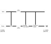
Many implements require pressures and flows lower than what my PT produces. One option is to use the auxiliary PTO circuit but I am using that for so many controls that I would likely have to use the main PTO circuit.
1.) The PTO pump is always running and dumping to the tank (correct me if I am wrong on that). Does running the flow through a pressure relief valve on an implement generate more heat than when the PTO is just dumping to the tank?
2.) If an inline flow restrictor is used, does that generate more load on a pump than a pressure relief? Basically, the question comes down to, should a pressure relief be put into the circuit before the flow restrictor?
I was going to buy some things to play around with and install with quick disconnects so that I could use them on various pieces of equipment. I am not going to worry about reverse capability at this point.
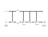
3.) Would the system run cooler or the same using a priority flow divider with the auxillary flow going to the tank versus a flow restrictor? This would give the advantage of being able to run an additional circuit if necessary (unlikely) and if it was cooler, that would also be a plus. An example is Surplus Center - 3/4" NPT 30 GPM ADJ PRIORITY DIVIDER VALVE RD575
I find it strange that the 3/8, 1/2, and 3/4 ported models are rated for the same flows - 30 gpm through a 3/8" port?
4.) Is there a big cooling, noise , etc advantage using a ball and spring pressure relief valve versus a poppet style? If there was, i might give up adjustability of the poppet style like this one Surplus Center - 1/2" NPT 20 GPM 1500-3000 PSI RELIEF VALVE RV-H4 versus the fixed Surplus Center - WJL-50-2000 HYD RELIEF VALVE
I am sure there are other questions I have not thought of.
Thanks for any and all input.
Ken
I apologize in advance for the length of this post.
I thought I would get your input on some general hydraulic flow questions and am posting it in the forum so others can learn from your input if needed. If you do not know some of the answers, I am not asking you to spend time researching them. Others, feel free to chime in.
Many implements require pressures and flows lower than what my PT produces. One option is to use the auxiliary PTO circuit but I am using that for so many controls that I would likely have to use the main PTO circuit.
1.) The PTO pump is always running and dumping to the tank (correct me if I am wrong on that). Does running the flow through a pressure relief valve on an implement generate more heat than when the PTO is just dumping to the tank?
2.) If an inline flow restrictor is used, does that generate more load on a pump than a pressure relief? Basically, the question comes down to, should a pressure relief be put into the circuit before the flow restrictor?
I was going to buy some things to play around with and install with quick disconnects so that I could use them on various pieces of equipment. I am not going to worry about reverse capability at this point.
3.) Would the system run cooler or the same using a priority flow divider with the auxillary flow going to the tank versus a flow restrictor? This would give the advantage of being able to run an additional circuit if necessary (unlikely) and if it was cooler, that would also be a plus. An example is Surplus Center - 3/4" NPT 30 GPM ADJ PRIORITY DIVIDER VALVE RD575
I find it strange that the 3/8, 1/2, and 3/4 ported models are rated for the same flows - 30 gpm through a 3/8" port?
4.) Is there a big cooling, noise , etc advantage using a ball and spring pressure relief valve versus a poppet style? If there was, i might give up adjustability of the poppet style like this one Surplus Center - 1/2" NPT 20 GPM 1500-3000 PSI RELIEF VALVE RV-H4 versus the fixed Surplus Center - WJL-50-2000 HYD RELIEF VALVE
I am sure there are other questions I have not thought of.
Thanks for any and all input.
Ken