My Solar Panel Power Project

   / My Solar Panel Power Project #1  

eepete

Platinum Member
Joined
Sep 30, 2009
Messages
962
Location
Efland, NC
Tractor
JD 4520, Kubota B21, JD 318
I decided to put up some solar photovoltaic panels. Here's an overview of the project:

Pete
 
Last edited:
   / My Solar Panel Power Project
  • Thread Starter
#2  
These pictures are shared with my 30 x 40 outbuilding project. The first shot is a before picture. I had a big pile of topsoil. If you look beyond and to the left of that, you will see a drywall bucket on a post. These are pipes that I put in for the solar project back during construction of the house.

The next shot is breaking ground. I had my new box blade on the JD 4520 and cleared the topsoil for the solar array field and inverter shed. You can see the materials for the project off to the right. The Kubota B21 TLB was there for moral support.

The 3rd shot shows the solar area with all its conduit in the ground (as I get ahead of my self a bit). You can see where the Morton Building will go, as well as the driveway into the building.

And finally, here is the Morton Building done. Final landscaping will happen this fall when the weather is better suited for that task.
 

Attachments

  • 1_before.jpg
    1_before.jpg
    511.3 KB · Views: 517
  • 2_solar_topsoil.jpg
    2_solar_topsoil.jpg
    659.5 KB · Views: 495
  • 3_course_grading.jpg
    3_course_grading.jpg
    760 KB · Views: 630
  • 4_ext_pre_final_grade.jpg
    4_ext_pre_final_grade.jpg
    217.1 KB · Views: 799
Last edited:
   / My Solar Panel Power Project
  • Thread Starter
#3  
This shot is the layout for the solar array and outbuilding. I am calling the outbuilding the Inverter Shed because it houses the electronic device that turns the DC into AC which is called an Inverter. The array consists of 36 panels stacked in 9 groups of 4. These are 216 watt panels, for a DC power of 7.77 KW. The two Low Voltage conduit goes to the north side of the inverter shed. There are two more conduits, a 2.5 electrical and a 3 PVC that go to the south side of the inverter shed. These will be used for power and an air line back from an air compressor that will be in the outbuilding feeding the garage so I do not have to listen to the compressor.

There are also two conduits that go south (up in this drawing) under the array. A 2.5 electrical, and a 3 PVC. This gives me a way to get power and other things to whatever the next project is that lies beyond the solar array. There is also a 1.5 conduit that goes to the DC combiner under the solar array. This devices parallels 3 clusters of 12 panels. It has fuses for each cluster and a DC surge protector. At the last moment, I added another 2.5 conduit going west (right) in case some project needed to go that direction some day.

So the inverter shed has 9 conduits coming up into it. The entire array has a circle of #6 copper buried around it as a ground. It comes up into the array on each side to ground the panels. The ground also goes up into the inverter shed at the power company feed (Piedmont Drop) and at the inverter. It also goes up to the combiner to provide ground for the DC protection. There is about 200 of ground wire here, and an additional 100 feet of 1.5 copper strap. This is burred about 3 down.
 

Attachments

  • 5_array_ground_layout.jpg
    5_array_ground_layout.jpg
    251.7 KB · Views: 519
Last edited:
   / My Solar Panel Power Project
  • Thread Starter
#4  
The next shot looks south from what will be the inside of the inverter shed. You can see the trench for future projects in the center. When the sun hit it, I knew I had the whole mess pointing pretty close to due south. You can see the wiggly trench to the DC combiner on the right, and the trench for the power company drop going to the left.

The next shot is this same future use trench after conduit was put in.

The next shot shows a titled view of it all. I know it is a little confusing... You can see the conduit up in the air where the inverter shed will be. You can see the trench for the power company drop to the left. Just beyond that is the trench for ground. You can see the zig zag trench for the DC combiner to the right. Just out of view is where the trench for things that go to the outbuilding will be.

The next shows is a view looking down the utility company drop. The ground trench is just to the left of that. I have not done the trenches to the outbuilding, but they go from the pole on the far right into the inverter shed area.

The final shot shows an opposite view. Here I am aligned with the ground trench. You can see the 1.5 conduit for the DC combiner, and further down the future use conduit. And in the background on the left is that drywall bucket with the conduit from the garage outbuilding. I put that in after all this trenching was filled up.

I wish I could have got an arial shot of all this. It was a fun problem to figure out how to dig all this up and that added some extra challenge to the project. So with all the conduit in place, ground wire, ground strap and ground rods (and the attendant county inspections) it was all covered up. I had reference stakes so I could go back later and drill the holes for the support rod for the solar panel array, and find the ground rods. Drilling into all this had to be pretty accurate given all this buried infrastructure.
 

Attachments

  • 9_trenches_w.jpg
    9_trenches_w.jpg
    732.5 KB · Views: 260
  • 8_trenches_SW.jpg
    8_trenches_SW.jpg
    737.3 KB · Views: 281
  • 7_trenches_looking_north.jpg
    7_trenches_looking_north.jpg
    738.3 KB · Views: 382
  • 6_trenches_looking_south.jpg
    6_trenches_looking_south.jpg
    793.9 KB · Views: 293
  • 10_trenches_east.jpg
    10_trenches_east.jpg
    800 KB · Views: 260
Last edited:
   / My Solar Panel Power Project
  • Thread Starter
#5  
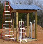
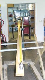
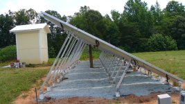
Now it is time to build the inverter shed. Carpentry is not my strong suite, and all I had for tools is a drill and hand skill saw. So I drilled holes with my post hold digger (PHD) and put 12 6x6 for the corners of this 6 foot by 8 foot shed. I put a 4x4 in the middle so I can add a screen door later. I wanted roof overhangs too. It took a come along and a little finesse to get the 2x8 at the top to pull together and get this all square.

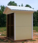
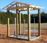
Next shot is after the roof was put on. After this, I had to frame in for my funny angled sides.

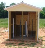
The next shot is looking into the shed. It is open to the north so the inverter can get lots of air. The shed had a 3/4 pressure treated plywood on the back, and 1/2 PT plywood on the sides. I then used Hardi Panel (cement fiberboard) for the sides. The funny angled sides are so that there are not 90 degree areas where wasps can make their nests. Between that angle and painting it white, no worries about wasps. I had to use Bondo (car repair stuff) to fill in the gaps on the Hardi panel and smooth out the looks of everything.

It took a lot of work to figure out how to cut the Hardi panel to get all those funny corners so they worked out. Later this fall, I will put a screen door on the right and screen on the left. The top will come down about 2 (the inside height is 8 feet and the bottom will also have about 2 of covering. The air compressor for the garage goes to the left.

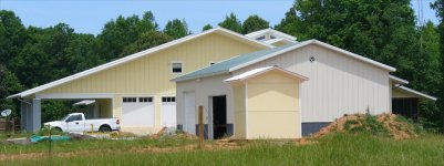
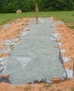
And yeah, after I got it done I kicked myself for not going 8 x 8. I did it this way so that the roof was 8 deep (6 inside plus a 1 overhang). At any rate, a 6 x 8 building with 6x6 posts 2.5 in the ground should be plenty sturdy. Hardi/cement fiberboard means no worry about boring bees (once the front is on). Eventually, as I do the final landscaping on this and the garage, there will be a gravel boarder around the shed.

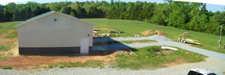
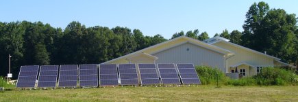
The last shot is a side view. The facia is Hardi board. I got 1x4 which forced me to use 1x3 rafters which made the whole framing of the roof funny. I should have got 1x6 board and used all 2 x 4. Oh well, it is hard to argue with something that is done. I would like to argue as to why it is hard to use contractions on this site. It sounds like this was written by Commander Data on Star Trek.
 

Attachments

  • 14_ished_side.jpg
    14_ished_side.jpg
    304.2 KB · Views: 325
  • 13_ished_front.jpg
    13_ished_front.jpg
    352.8 KB · Views: 328
  • 12_ished_roof.jpg
    12_ished_roof.jpg
    661.7 KB · Views: 385
  • 11_ished_frame.jpg
    11_ished_frame.jpg
    528.7 KB · Views: 393
   / My Solar Panel Power Project
  • Thread Starter
#6  
So here is a picture of the roof lines of the place. The inverter shed, outbuilding garage, garage on the house, and the house. Got the angles right, looks like a man built set of mountain peaks...

And here is a picture of the PHD on the tractor because everyone likes tractor pictures :thumbsup:.
 

Attachments

  • 15_rooflines.jpg
    15_rooflines.jpg
    508.1 KB · Views: 526
  • 15a_phd_on_4520.jpg
    15a_phd_on_4520.jpg
    541.3 KB · Views: 392
   / My Solar Panel Power Project
  • Thread Starter
#7  
Now it is time to focus on installing the supports for the panels. The aluminum rails that hold the panels are supported by 3/8 inch stainless steel threaded rod. There are six rods supporting the two rails that hold 4 panels which weight about 50 pounds each. So after a little calculating and measuring, I drilled some 16 foot long 2x4s with the holes where I wanted the rods. It took 12 2x4s to support the 54 rods needed for all this.

After drilling 54 holes with a 6 inch auger where the hole had to be within 3 inches of the right spot, I am starting to get the hang of using a PHD. The next show shows the rods in the holes in with concrete. It took about 2.25 yards to pour fill the holes and put a concrete pad in the inverter shed. I was short about .1 yards. This shot also shows the start of a pea gravel base on landscape cloth. You can see the post for the DC combiner in the middle of the array.

This has not been a cool summer. Here I am half way done with the 1st of 9 sets of rails and panels. If you look at the bottom of the picture, you can see inch tall pieces of 4 inch PVC pipe. These will be filled with concrete once things are set up right. A mistake I made was this: I should have put the PVC sleeves on the front support rods before any panel mounting started. The 2x4 forms had everything lined up right. The weight of all this pushed the rods forward a bit, and tweaking the position of the rails made things worse.
 

Attachments

  • 16_rod_forms.jpg
    16_rod_forms.jpg
    384.5 KB · Views: 473
  • 17_concrete_gravel.jpg
    17_concrete_gravel.jpg
    667.3 KB · Views: 547
  • 18_first_pannel_hot.jpg
    18_first_pannel_hot.jpg
    535.8 KB · Views: 523
Last edited:
   / My Solar Panel Power Project
  • Thread Starter
#8  
Here is the 1st group of panels done.

The next shot shows the whole area covered in gravel, and the brackets that hold the rails up ready to go. I also put neoprene washers on both sides of the angle brackets that hold up the rails. This reduced the contact area of the stainless hardware and the aluminum, and gave the whole system a little more room for metal to expand and contract with temperature.

All the panels are up and the PVC sleeves are filled. The 1st four groups are a little off, the last 5 are better. Seems like you only know how to do something after you are finished.

Here is a closeup of the ground connections. You can see two #6 wires going off to the left. They go up onto the array and ground the panels for both lightning and ground fault safety. You can see where the copper strap connects in. This is the ground wires that were buried back in October some 9 months ago. You can also see a zinc sacrificial anode that is connected to all this so if there are any galvanic corrosion problems, the anode can loose. I later soldered the #6 wires together with tin solder (plumbing solder). So the split lugs give the strength, the solder gives a good connection for even the smallest currents.

The inverter has a GFI for the DC. If there is any leakage between the DC connections and ground, it shuts down the connection to the DC. Between that and the grounding of the array, things should be safer. But the panels have about 400 volts open circuit, that drops down to about 340 under load when the entire array provides about 22 amps. Important safety tip: Do not disconnect any DC leads when the system is under load.
 

Attachments

  • 22_array_ground.jpg
    22_array_ground.jpg
    638.1 KB · Views: 381
  • 21_array_side_view.jpg
    21_array_side_view.jpg
    563.4 KB · Views: 654
  • 20_array_area.jpg
    20_array_area.jpg
    642.5 KB · Views: 274
  • 19_first_array_done.jpg
    19_first_array_done.jpg
    600.5 KB · Views: 324
Last edited:
   / My Solar Panel Power Project
  • Thread Starter
#9  
So here is the entire array done. This winter when it is not Africa Hot out, I will get some buddies and clean up the four on the right. It is about a 2 degree error on some.

I needed to figure out how to series connect the groups of 12 panels so I was not trying to think out in the field. This also let me figure out where to put the DC combiner and what length of leads to order to connect the panels to the combiner. All the lengths are matched so the voltage drop is the same. This is shown in the .pdf file.

The utility company showed up to connect to the commercial mains. I had 120 feet of 2.5 inch conduit buried for them. I did this because it crosses the geothermal heat pump fields, so I had to had dig where the intersection was to be sure I did not hit any buried geothermal line. They should have all been down at 5 feet deep, but there were a few places we hit rock and they came up a bit. I did not find any of the geothermal lines, but if I had not been careful I am sure I would have. The dug in about 50 feet of line. Most of all, it is a picture of another piece of equipment :thumbsup:.

They wired up to the meter base, put in a fancy meter that keeps track of what you push into the grid (where I get paid) and what you take from the grid (where I pay them).
 

Attachments

  • 23_final_array.jpg
    23_final_array.jpg
    169.9 KB · Views: 563
  • 24_solar_array.pdf
    13.1 KB · Views: 285
  • 25_burry_mains_drop.jpg
    25_burry_mains_drop.jpg
    604.2 KB · Views: 346
  • 26_meter_connection.jpg
    26_meter_connection.jpg
    326.5 KB · Views: 860
   / My Solar Panel Power Project
  • Thread Starter
#10  
I turned it all on and it worked :D
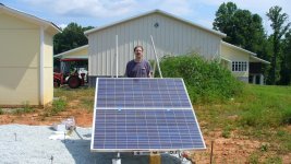
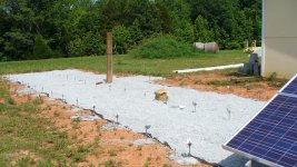
. It was cloudy and rainy today, so we only put out about 250 Watts of power :(. But that is OK, tomorrow is another day and I will post when I have some real power to brag about. I will also take a shot of the electrical side of it all in the inverter shed.

I've got a little written blurb I am working on that explains a bit about grid tie systems and why I think they are worth the effort. I will be posting that in a few posts in the days ahead.

Pete
 
Last edited:
 
Top