SOLAR MELTDOWN......almost a FIRE!!!

   / SOLAR MELTDOWN......almost a FIRE!!! #1  

Boeing

Platinum Member
Joined
Sep 14, 2010
Messages
617
Location
Botetourt, Va
Tractor
kubota L3010
Guys, I have posted several Solar questions/comments here in the past 7 years or so but this one really has me confused. I have 4 panels on the roof; 100W each. They go to a fuse box (2) 20 AMP fuses (I think) Then, the red wire went to a Volt Meter and on to the controller. The black lead went straight to the controller. There has never been a problem or issue. The V meter showed zero at night, 12V at dawn, "up to" 14V and during "float" charge it might hit 18V for about 45 seconds on a bright day.
I noticed last week that it was showing 20 Volts....knowing that's not right I "thumped" it and it came back to 12V. OK, that's like the old analog gauges on the 727. It happened again several times. The green light on my controller started blinking indicating that it was going into "float mode" (I've read about this but it isn't clear what that means) Anyway, it continued to blink until almost dark and the voltage still showing 14ish....not normal that late in the day.
I started smelling insulation burning.....uh oh....,When it got dark the blinking green light and both yellow and red lights on the controller WENT OUT. Normally the green stays on for an hour or two then the green and yellow lights stay on indicating that I am going below the 12.8 Volts. If I get a shower (pump) and use lights long the green goes out and the yellow is the only light. If it has been cloudy for a few days it will actually go yellow AND red.....Voltage is below 12.3 or something....(I don't like to see that)
I know this is getting too long, I apologize....anyway, all lights went out and I smelt insulation. The next morning, all lights are still out and SUN is shining. (It should be showing "at least" 12 Volts and green/yellow lights on) I pulled the panel out and looked behind it.
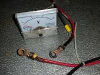
The RED wires on both sides of the Voltmeter were burned, the POS pole of the V-meter was burned OFF!!.
This alarms me greatly as my panel is PLYWOOD, screwed to 2X4's....easily a FIRE!!!!
The Voltmeter was 7 years old, installed on day one of my solar system. Admittedly, it was an E-Bay CHINESE piece of ....well, anyway. I've only seen the cheapies and/or LED meters, also cheap, and constantly drawing current. I put a new heavy red wire in with no voltmeter and all seems OK.....but I sure miss the Voltmeter.

Comments, advice...possible causes? Thank you in advance. Rob W
 

Attachments

  • Vmeter Rear.jpg
    Vmeter Rear.jpg
    279.8 KB · Views: 292
  • V. meter front.jpg
    V. meter front.jpg
    266.4 KB · Views: 281
   / SOLAR MELTDOWN......almost a FIRE!!! #2  
It a can be from a number of causes, all due to age. Solar in not invincible, the technology fails. Do you have a voltage regulator coming off your panels? When you talk about colored lights, is that in your voltage regulator? I would assume you do and it is the first place I would look. Regulator fail. THey are managing juice that is fluctuating, puts wear on the coils. Next I would look at wire condition. Got Squirrels? Mice? They may have chewed up a line. Third, your batteries. When they fail they can fail in this manner. Finally it could just be the meter letting you down. as for the cheap chinese stuff. Not much is manufactured in the USA. That said, I would consider a nice digital meter next time around. There are some good ones on the net for sure.

Just adding an edit. Not sure what your batteries are but they are hard to home test unless you have a good tester. You may need to take them in.
 
   / SOLAR MELTDOWN......almost a FIRE!!! #3  
not sure about this. was the volt meter in series with the controller? i don’t think your volt meter was made to handle full load amps.:confused3:
 
   / SOLAR MELTDOWN......almost a FIRE!!! #4  
Most voltmeters I've seen are in parallel. When your battery is partially discharged in the morning, it will draw a much higher current because of the voltage difference. Without knowing what type of charger you have, I will assume a voltage controlled charger... Max current will be drawn until the battery voltage comes up.

The panels limit the current produced, but you are pulling less than 20 amps because of the fuses. Regardless, you will produce heat, and the constant heating and cooling of the bolted connections can cause them to loosen. Then they get very hot..

I would either do a bit of internet research, or consult a qualified solar tech....
 
   / SOLAR MELTDOWN......almost a FIRE!!! #5  
You don't put a volt meter in series. You put a volt meter in parallel. An ammeter goes in series. As mbohuntr mentions, they are not designed to take that kind of load. You are lucky you didn't blow it out a long time ago. Voltage is a measure of potential difference (pressure) and must be measured across something. Current (amps) is a measure of flow (volume).

You measure the voltage across something for example the terminals of a battery or the terminals of your solar panel. A volt meter has a very high resistance because it is designed to only pass a small amount of current which is all that is necessary to measure the voltage and protect the meter. Hope this helps.
 
   / SOLAR MELTDOWN......almost a FIRE!!!
  • Thread Starter
#6  
Help me to understand this....I put the V-meter "in-line". The POS line went to the POS terminal and continued on to the controller. The NEG wire did the same on the NEG side of the V-meter. I "think" that is "SERIES". HOW would you wire a V-meter in "Parallel"? I did have and try to wire in an AMPMETER using the same wiring procedure. It never worked at all...???? I figured that it was a cheap amp meter. I wrote the seller and he said that I needed a "SHUNT" and sent me a ceramic thing with a steel bar and a contact on each end. He DID NOT tell me HOW to wire this gizmo and I never tried it. DUH....:confused2:
 
   / SOLAR MELTDOWN......almost a FIRE!!! #7  
Whoah! How many wires does this volt meter have? A typical meter (volt or amp) has two wires. In series would be attaching the positive lead to the solar panel positive and the negative terminal to the positive side of the controller. This is how you would attach an ammeter. For a volt meter you want parallel so positive terminal of the volt meter to the positive terminal of the solar panels. The negative terminal of the volt meter to the negative terminal of the solar panels. Substitute any power source for solar panels e.g. battery.

Maybe your meter was in parallel if the following was true: 1) the positive lead from your panels went to the meter and a second lead from the same terminal went to the positive side of the controller. 2) Same for the negative side. If this is true the meter was in parallel with the panels.
 
   / SOLAR MELTDOWN......almost a FIRE!!! #8  
From looking at the pictures and description it appears that your voltmeter was actually in parallel as it should have been, but it was being used as a terminal block between the solar panels and the load. If the red wires had a bad connection on that terminal it would overheat the terminal and cause the damage that you have.
 
   / SOLAR MELTDOWN......almost a FIRE!!! #9  
The best thing you can do is draw up an accurate wiring schematic of your system the way it was before the meter melted. Then post that picture here so everyone is clear on what you had.

Then draw up another wiring schematic of the way it is now that the volt meter is not in the system.

A schematic is extremely handy and important for your own records if and when you have to troubleshoot your system, or make modifications. ;)
 
   / SOLAR MELTDOWN......almost a FIRE!!! #10  
Help me to understand this....I put the V-meter "in-line". The POS line went to the POS terminal and continued on to the controller. The NEG wire did the same on the NEG side of the V-meter. I "think" that is "SERIES". HOW would you wire a V-meter in "Parallel"? I did have and try to wire in an AMPMETER using the same wiring procedure. It never worked at all...???? I figured that it was a cheap amp meter. I wrote the seller and he said that I needed a "SHUNT" and sent me a ceramic thing with a steel bar and a contact on each end. He DID NOT tell me HOW to wire this gizmo and I never tried it. DUH....:confused2:

You really need some detailed explanations to help you be safe. Series means ALL the current must pass thru the meter.. only recommended for small currents (Ammeter), and I've never seen one in series for voltage. A SHUNT is a bar with a current limiting resistor in it calibrated to the meter range.

shunt resistor - Bing

A voltmeter contains a similar internal resistor so the voltage is measured across the resistor. If you try to measure voltage with a handheld meter, placing both leads on the same wire, it will read zero. If you measure across a resistor of some type, you will read a voltage because the potential is different from one side compared to the other.

I think you would like some stuff on Youtube.
 
 
Top