In Over My Head With Electric Motors

   / In Over My Head With Electric Motors #1  

Bird

Epic Contributor
Joined
Mar 20, 2000
Messages
43,753
Location
Corinth, Texas
Son-in-law's Ryobi Plate Joiner quit, so he sent it to me to see if I could fix it. The obvious problem was that the red wire from the stator to the front brush got against the rotor, rubbed the insulation off and frayed the wire. Wasn't hard to cut the little bad spot out and splice the wire back, and everything else "looks" like new, but it still doesn't work. I've done the obvious for an amateur; i.e., checked continuity through the switch and wires to the brushes, but know very little about electric motors. Anyone have any guesses as to what might be wrong or what I could do to make this motor run again?
 
   / In Over My Head With Electric Motors #2  
Bird, I'm no expert and this is probably too obvious, but is it possible when the wire (presumably) shorted out the unit that it tripped a thermal shut-off....is there a reset button?

Only other thought is you may have a dead spot on the windings....try turning the shaft a bit and then return power.
 
   / In Over My Head With Electric Motors
  • Thread Starter
#3  
Thanks, Wasabi, but no reset button or thermal shut-off that I know off. I've had the motor completely apart and back together (twice) and I can turn the rotor quite freely by hand, but nothing happens when I plug it in and hit the switch.
 
   / In Over My Head With Electric Motors #4  
you might check continuity from the end of the plug all the way thru the switch, just in case when it shorted, it burned the power cord??
heehaw
 
   / In Over My Head With Electric Motors #5  
Bird, You didn't say if it was series wound (most likely) or shunt wound. Anyway, I think I followed what you did. You didn't say that you checked continuity through the brushes or ... oh well.

I assume you have an ohm meter with test leads to check continuity. Did you check with your ohm meter across the "hot" and "neutral" prongs of the power plug while turning the switch on and off? You should get essentially an "infinite" (real large) Ohm reading with the switch off and a lot lower value with the switch on. You might give the motor a spin with the switch on while checking continuity in case there is something "funny" with the commutator/brush contact. If this high/low resistance with the on/off switching doesn't happen then there is an "open" somewhere. An open could be bad brush contact, an armature or stator wire burned out from the short or something else.

The ohm meter should show a fairly low reading when placed across the stator winding (lower than with the rotor and stator in series) Likewise the rotor windings can be checked individually for continuity and should be approximately equal to each other. If one is open then it has a broken or burned out wire. Here is a couple ways to test the rotor for continuity with your ohm meter: 1. connect the ohm meter leads to the brushes and slowly rotate the motor. You should see a series of readings that are about equal, maybe with "glitches" in between since the brushes break contact with one commutator plate and connects to the next as you rotate the shaft. 2. If the rotor/armature is removed you can touch your ohm meter leads to opposite pairs of commutator plates one at a time and they should be about equall in resistance. If one is way high it is burned out or broken. If one is way low it is shorted.

Another test, with the armature out in your hand, is to ohm between each of the commutator plates and various places where there is bare metal on the armature. Continuity (a lot lower ohm reading than "infinity") between any commutator plate and any bare metal of the shaft or armature indicates a winding or commutor plate is shorted to the armature core laminations or the shaft.

These are repairable conditions if you don't mind carefully unsoldering the winding on the armature, unwinding it, counting the turns, and replacing it with new wire or if able, insulating a short or connecting an open.

These motors are fairly high speed but with care you can put the same gauge wire back or otherwise not unballance it too much when fixing a short or open. At worst you will fail, but so what, you don't have a working tool now,do you? Maybe you can fix it AND it won't vibrate too much from being out of ballance.

Let us know what happens. I would be happy to try to help further if you like.
 

Attachments

  • 6-172961-SeriesMotor.jpg
    6-172961-SeriesMotor.jpg
    17.9 KB · Views: 62
   / In Over My Head With Electric Motors
  • Thread Starter
#6  
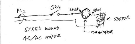
Thanks to all of you for your help. Patrick, I think you've got it. <font color=blue>series wound (most likely) or shunt wound</font color=blue>. I have no idea what that means or what the difference it, but from your sketch, I'm guessing you're right about series wound. On this tool, the white wire from the power cord goes directly to the rear brush, while the black wire goes through the switch to the stator, then a red wire (the one that was badly mangled) from the stator to the front brush. I had noticed initially that neither of the brushes seemed to be making contact all the way across their face (scratches in the middle of each one), although they show every little wear.

By cleaning the grooves between the commutator plates and using a little emery cloth to clean the face of the commutator plates and the face of each of the brushes, I got it to running (twice). Just a couple of problems./w3tcompact/icons/frown.gif It ran as long as I kept the switch on, but once shut off, it would not start again, and while running I could, through the vents, see a stream of fire running around the commutator, and when I took it apart again, the brushes had little grooves or scratches on them. Some of the windings just below the commutator appear to be discolored, but not actually burned or broken. Does this mean, as I suspect, that there is a short in there somewhere?

And as far as rewinding one, I'm afraid that's a little out of my league.
 
   / In Over My Head With Electric Motors #7  
Bird, Is there more than one way to put the brushes back in? They may eventually wear to fit but the process can be speeded up by lifting a brush and placing a small strip of fine emery cloth over the comutator, lowering the brush down to it, and rocking the armature back and forth to shape the brush while pressing down firmly on the brush. Also when "cleaning" the commutator use extremely fine emery cloth or the induced roughness will cause increased sparking. Make sure NO GRIT is embeded in a brush or commutator to cause accelerated wear.

If your motor looks like my schematic then it is series wound (it could be on the quiz). When you ohm the individual coils of the armature by contacting opposite pairs of commutator plates the resistance values should be nearly equal. If not you have a problem with the armature.

Patrick
 
   / In Over My Head With Electric Motors
  • Thread Starter
#8  
Patrick, the brushes are rectangular shaped so they only go in one way (or can be turned 180 degrees). And I did shape them properly (I think)./w3tcompact/icons/tongue.gif And I think I got everything clean and as smooth as possible using a tiny screwdriver blade, terry cloth, and 90 psi air after the emery cloth.

<font color=blue>When you ohm the individual coils of the armature by contacting opposite pairs of commutator plates the resistance values should be nearly equal</font color=blue>

I think I must not be able to do this right 'cause I got no continuity at all contacting opposite pairs of plates, but could get continuity from one plate to the plates within 90 degrees of each other on most (but not all) plates. But maybe it was my clumsiness in handling the leads and those very small plates 'cause when I assemble everything with one side cover off, then hold the leads firmly against the brush holders and very slowly turn the rotor, I got continuity at only one particular spot (so that would be 180 degrees or opposite pairs of plates). I could then slowly turn the rotor 180 degrees and get the same continuity there (ohm meter reading "005" both ways).

<font color=blue>If not you have a problem with the armature</font color=blue>

Methinks therein may lie the problem. I think it's time for the factory authorized service center./w3tcompact/icons/wink.gif

This darned tool is practically new and should be under warranty, but my son-in-law kept the manual, but not the receipt so he doesn't remember when he bought it and didn't send in a registration card./w3tcompact/icons/frown.gif Maybe he'll learn.

And thanks again for all your help.
 
   / In Over My Head With Electric Motors #9  
From what you described about the motor starting one time and not the next, it sounds like one or more of the windings is open. If the rotor happens to stop on an open winding it will not start. If this is the case you should be able to manually turn the rotor a partial turn and then it should start. This means the motor is toast.
 
   / In Over My Head With Electric Motors #10  
When you ohm the individual coils of the armature by contacting opposite
pairs of commutator plates the resistance values should be nearly equal

Let me try a different way... The electrical resistance of the various "poles" of the armature should be approximately equal and physically conected in a symetrical manner. If either of these is not true at any time, then the armature is definitely bad. As you test the armature you should get results that repeat as you go from conducting pair (of plates) to conducting pair. Any break in symetry is a failure to pass the test. Any significant variation in resistance (ohms) is a failure to pass the test.

But why should he keep his waranty papers when you will fix everything for free?

Patrick
 
 
Top