compressor quit a while back (we had a spare, so not in too big hurry to figure out what happened). I disconnected from the 220 romex. power cord has black, white, and green wire. Have a fluke 75 multimeter if any of y'all can explain to me what do. Set to ohms? anyway be specific as dont understand electricity very well.
when you say "compressor quit" what does that mean? was there smoke? does the motor just sit and buzz when you plug it in? is there ANY reaction when you plug it in?
start of basic troubleshooting for a motor...
step 1: remove the load from the motor. do this by loosening belts etc.
step 2: attempt to turn the rotor by hand. what happens?
step 3: plug in motor. what happens?
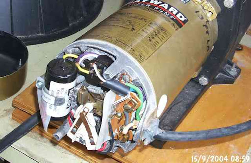
the motor for your compressor is undoubtedly a capacitor start induction type. the picture below is of a pool pump motor, but it is the same type as your compressor.
your issue is probably the starting capacitor, and not the windings. induction motors have no defined rotational direction; absent any "push" in one direction or the other, it will just sit there and hum (and draw a lot of current). a capacitor start circuit is thus used to force a phase change in one set of windings (aka the start winding) and give the motor a direction. once up to speed, the capacitor start circuit is then disabled, usually via a mechanical centrifugal cutout. for this reason, if the capacitor is found to be bad it is sometimes a side effect of the mechanical cutout not releasing, which causes the capacitor to fail over time.
replace the capacitor, and check the centrifugal cutout for corrosion. the cutout is typically on the end of the shaft nearest the AC wiring entry.
at 9 o'clock in the picture below, you can see the cylindrical capacitor (condenser for you old skool folks), and to the right of it you see the centrifugal cutoff switch. it consists of two assemblies, the mechanical portion and the electrical portion.
the mechanical bits are attached to the end of the rotor shaft and is typically made up of two small flyweights, cam'd against spring tension. the faster the motor spins, the "flatter" the assembly gets as the centrifugal force of the flyweights pulls against the spring tension. in the pic below, you can see one of the two flyweights and one of the two springs. you can also see an "arm", co-linear with the rotor shaft, that is currently riding on the white plastic switch assembly, closing the circuit. in this condition, at rest, the capacitor and start winding(s) are switched in to the circuit.
as the rotor accelerates, the flattening out of the mechanical portion of the cutout disconnects the two overlapping copper contacts (located at 6 o'clock) and the start winding is no longer powered. motor operation continues at the design speed, typically 1725RPM (1800RPM nominal, less the slip, with a 4 pole winding) or 3450 (3600RPM, less the slip, with a 2 pole winding).
this particular motor also has a thermal cutout, located at the 12 o'clock position in the picture below. these can also fail, which leads to a completely inoperative motor. note that the thermal cutout may have failed because the motor overheated. if you replace the thermal cutout and don't fix the reason the motor overheated in the first place, you'll be back in there again in no time.
Wrooster