You are using an out of date browser. It may not display this or other websites correctly.
You should upgrade or use an alternative browser.
You should upgrade or use an alternative browser.
Attention electronics experts
- Thread starter PineRidge
- Start date
/ Attention electronics experts
#1
OP
PineRidge
Super Member
OP
PineRidge
Super Member
The only thing that made me feel good was that I didn't build the board. Here's the simple schematic of the project.
I am looking for someone that could assist me in making one of these timers that not only works but is also presentable, I would be responsible to house and mount it. Otherwise I'll be forced to dig out the old Weller and hack one out that looks worse the prototype. /forums/images/graemlins/crazy.gif
If you would be interested please let me know as your help would be really appreciated.
Attachments
I can do it, was a certified NASA soldering instructor back in the 60's when I worked for Hughs Aircraft. Even have most of the componets in my shop. Think the only item I won't have is the regulator IC, kinda a off the wall voltage. I'll look at the schematic again when I finish this post and see if 12 volts might work, that is usually what I use when working with 555's.
Ya, don't understand why they chose 15 volts except maybe the voltage drop between 18 and 15 will result is less power being dropped in the regulator and therefore less heat dissipated. Would also add diodes across the relay coils if they aren't built into the relays..
Still don't understand the designers logic, makes no sense to use 15 volts then drop it through a resistor for a 12 volt fan.
Still don't understand the designers logic, makes no sense to use 15 volts then drop it through a resistor for a 12 volt fan.
OP
PineRidge
Super Member
Bob maybe some of the following will explain why they did, what they did:
Batteries are required to power your fan in the field which can be cumbersome and expensive. An on/off switch of some type will help conserve batteries. A simple momentary push button switch may be the most elegant solution as a strong fan only needs to be turned on for a few seconds at a time. Rechargeable NiMh batteries can be used to soften the financial blow caused when the fan is accidentally left on. Multiple cells can be wired in series to achieve the required voltage. A typical high quality setup would be 8 AA cells with a momentary switch. Other more expensive battery options are 12v NiMh clusters used in RC cars/planes and cordless drills. The fan controller shown here uses (2) 9v cells to keep the controller small and lightweight and a voltage regulator to control the current. The controller also features a timer circuit which automatically shuts the fan off.
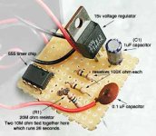
This timer is a monostable circuit which uses the venerable 555 timer chip. The 555 can only handle 15v so the power must be stepped down from 18v before entering the circuit. The duration of the timer depends on the values of (C1) and (R1) in the following examples. The parts shown here give a calculated run time of 22 seconds. Parts include: 2"x3"x1.5" project box, momentary pushbutton switch (special double pole 'DP' switch), LED w/resistor, 1/8" plug for fan (optional), circuit board, 555 timer, 15v voltage regulator, 0.1uF (micro farad) capacitor, 1uF capacitor (C1), (2) 100k ohm resistors, 20M ohm resistor (R1), 30 ohm resistor, (2) 12vdc 1A reed relays, (2) 9v battery connectors and (2) 9v batteries. Tools include a small soldering iron, thin solder, thin jumper wire and safety glasses.
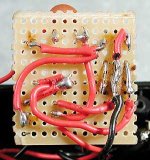
The voltage regulator tames the batteries to a steady 15v and the timer circuit eats up about 1.6v more. Typically 13.4v of current is supplied at the fan producing strong air flow from the slightly overclocked fan. The 555 chip usually has a marking near pin #1, in this case it's a small circle. The 1uF cap (C1) shown here was salvaged from and old television/target to save a trip to the electronics store. This image does not show the additional 2 reed relays and 30 ohm resistor needed to fix a problem with unintentional battery drain. These components are shown in the schematic below.
Adjusting the values of (C1) and (R1) changes the duration of the timer. It is possible to substitute (R1) for a potentiometer to provide stepless time adjustments. This example uses (C1)=1uF and (R1)=20M ohm and times for 26 seconds although calculations say it should time for 22 seconds. Change the value of (R1) to 10M ohm to set the timer for about 12 seconds or 5M ohm for about 5 seconds.
This is the revised schematic for the fan controller circuit wich eliminates the problem of unintentional battery drain. It uses two reed relays to isolate the timer circuit from the power source. The relays are small enough to fit inside the pictured project box alongside the batteries and the additional resistor will fit on the main board. It is also possible to use smaller switching components like transistors in place of the relays. This circuit uses a double pole (DP) switch which triggers the two separate circuits at the same time providing 12v at the fan. The toggle style power shutoff switch has been eliminated from the design but is easy to add next to the battery if desired. Large fans running at 12v can easily vent or mix in 2-3 seconds, 26 seconds is a little overkill. This circuit features a bit of circuit protection so crossing your output wires on accident shouldn't cause any harm.
Maybe some of this information will make sense to you. I'm confused at best.
Batteries are required to power your fan in the field which can be cumbersome and expensive. An on/off switch of some type will help conserve batteries. A simple momentary push button switch may be the most elegant solution as a strong fan only needs to be turned on for a few seconds at a time. Rechargeable NiMh batteries can be used to soften the financial blow caused when the fan is accidentally left on. Multiple cells can be wired in series to achieve the required voltage. A typical high quality setup would be 8 AA cells with a momentary switch. Other more expensive battery options are 12v NiMh clusters used in RC cars/planes and cordless drills. The fan controller shown here uses (2) 9v cells to keep the controller small and lightweight and a voltage regulator to control the current. The controller also features a timer circuit which automatically shuts the fan off.
This timer is a monostable circuit which uses the venerable 555 timer chip. The 555 can only handle 15v so the power must be stepped down from 18v before entering the circuit. The duration of the timer depends on the values of (C1) and (R1) in the following examples. The parts shown here give a calculated run time of 22 seconds. Parts include: 2"x3"x1.5" project box, momentary pushbutton switch (special double pole 'DP' switch), LED w/resistor, 1/8" plug for fan (optional), circuit board, 555 timer, 15v voltage regulator, 0.1uF (micro farad) capacitor, 1uF capacitor (C1), (2) 100k ohm resistors, 20M ohm resistor (R1), 30 ohm resistor, (2) 12vdc 1A reed relays, (2) 9v battery connectors and (2) 9v batteries. Tools include a small soldering iron, thin solder, thin jumper wire and safety glasses.
The voltage regulator tames the batteries to a steady 15v and the timer circuit eats up about 1.6v more. Typically 13.4v of current is supplied at the fan producing strong air flow from the slightly overclocked fan. The 555 chip usually has a marking near pin #1, in this case it's a small circle. The 1uF cap (C1) shown here was salvaged from and old television/target to save a trip to the electronics store. This image does not show the additional 2 reed relays and 30 ohm resistor needed to fix a problem with unintentional battery drain. These components are shown in the schematic below.
Adjusting the values of (C1) and (R1) changes the duration of the timer. It is possible to substitute (R1) for a potentiometer to provide stepless time adjustments. This example uses (C1)=1uF and (R1)=20M ohm and times for 26 seconds although calculations say it should time for 22 seconds. Change the value of (R1) to 10M ohm to set the timer for about 12 seconds or 5M ohm for about 5 seconds.
This is the revised schematic for the fan controller circuit wich eliminates the problem of unintentional battery drain. It uses two reed relays to isolate the timer circuit from the power source. The relays are small enough to fit inside the pictured project box alongside the batteries and the additional resistor will fit on the main board. It is also possible to use smaller switching components like transistors in place of the relays. This circuit uses a double pole (DP) switch which triggers the two separate circuits at the same time providing 12v at the fan. The toggle style power shutoff switch has been eliminated from the design but is easy to add next to the battery if desired. Large fans running at 12v can easily vent or mix in 2-3 seconds, 26 seconds is a little overkill. This circuit features a bit of circuit protection so crossing your output wires on accident shouldn't cause any harm.
Maybe some of this information will make sense to you. I'm confused at best.
Yep, helps to understand the thought process... I would have done it a little different but what he has will work.
What are you planning to use for the batteries (power)? The circuit can be made more efficient depending on what it is going to be powered from. If you are going to use two 9 volt batteries it is fine the way it is, if you are going to power it from a tractor battery we can make some improvements /forums/images/graemlins/smile.gif
What are you planning to use for the batteries (power)? The circuit can be made more efficient depending on what it is going to be powered from. If you are going to use two 9 volt batteries it is fine the way it is, if you are going to power it from a tractor battery we can make some improvements /forums/images/graemlins/smile.gif
SPIKER
Elite Member
Hey PR (mike) it never seems to amaize me the things you get you're self into /forums/images/graemlins/wink.gif why are you building a device like this? just wondering as there are commercial industrial timers available already packaged. you might find one here at CPI surplus in shelby oh, http://www.cpisurplus.com the gilr there at the desk is very knowlqageable and they are partnered with a place a few min away who deal in electrionics. one sorce for mass production in the lower to even high quanities is RBB in shreve ohio which is not all that far from you they are out in the sticks near wooster, (you can make a stop to the newier RuralKing there then too /forums/images/graemlins/wink.gif) shereve is kind of south west about 20 min from them. I think they have a webv site too, I graduated with one of the primary workers there, both with electronic engeneering degrees. I gave up with electronics except for myself as a hobbie instead focused on industrial electrical equipment design & engeneering...
anyhow if ya need some help let me know
Mark M /forums/images/graemlins/smile.gif
anyhow if ya need some help let me know
Mark M /forums/images/graemlins/smile.gif
mwechtal
Silver Member
Hey Pineridge,
You could always whip one up using the dead bug method. You know, put the 555 upside down, and solder the components to it. Kinda looks like a dead bug huh.
I bet they don't teach that in NASA certified soldering courses!
Of course, I've never used this method. I was in a room where it was being done once, but I didn't inhale. /forums/images/graemlins/wink.gif
Mike
BB_TX
Veteran Member
- Joined
- Jan 29, 2002
- Messages
- 1,927
- Tractor
- JD 950
You can buy small hobby circuit boards at Radio Shack made just for that purpose. They come in all sorts of sizes and configurations for creating custom circuits. Much easier than that type board on yours. Components are soldered to the board, not each other. Much neater and cleaner. Get one and a small iron and go at it.