B7800 Question

   / B7800 Question #11  
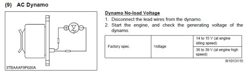
Thanks for the information. I don稚 have any need to upgrade right now. I just want it to charge the battery. I wonder if I might have a bad wire. From what I致e read tonight the dynamos rarely go bad. They are pretty simple in construction. Any idea what voltage should I expect to get off the dynamo when I test it?

Yes, they rarely go bad.
An electrical system for those old tractors is very simple. I'll go through the parts one by one with you over the next few days if you like.

BTW, from the symptoms you have mentioned so far I would say there is a good bet your problem is a bad Voltage Regulator - it is what Cabin Dweller is calling the IC regulator, because some new voltage regulators have Integrated Circuits insteas of solenoids. Which ever type it is - either IC or solenoid type, voltage regulators not only regulate voltage, but they also prevent the battery from slowly discharging back through the generator coils overnight. You can check that several ways, but the simplest is by charging up your battery as usual in the evening... and then when you put it back in the tractor DO NOT hook up both leads to the battery. Check battery voltage in the morning and it should be what it was the night before. Hook it up and the battery will start the tractor fine.
Next afternoon, charge up the battery and do the same tests but this time hook up the battery as normal and let it all set that way overnight. If the battery is flat the next morning, it is most probable you have a bad Voltage Regulator. They do wear out. Replace it with whatever type you have in there now. In the aftermarket sometimes the old-fashioned solenoid type are better than the inexpensive IC device type. Butif you can get OEM you may be able to use either one.

OK... Onwards to the way a basic electrical circuit works in our little tractors.

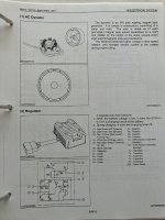
1. It always starts with some kind of a device that rotates coils & magnets past each other, because that creates Alternating Current. The magnets and coils are wound and spaced to that in the diesel's 1000 to 3000 rpm range it device will put out 12 to 20 volts.
Usually the device itself looks like a can with a pulley on one end and is spun by a fan belt. In middle USA speak, it is either a "generator" (what you are calling a dynamo) or "alternator" depending on if the coils are rotating or the magnets are rotating. Either one will work for you. They are very reliable and easily rebuilt.

There are two wires coming from this device. You don't need to disconnect them, just clip your digital voltmeter across the two wires, start the motor, and see what you get. More rpm will equal more volts. Expect to see 12 to 20 volts and note if it is AC or DC on the meter.

This voltmeter test coupled with the overnight test described above is going to tell us where to look next.

2. BTW, it seems an aside, but before we trip over terminology we ought to get on the same page about whether you have a generator or an alternator - not that it matters to the tractor. It can use either. It's confusing because in most English speaking countries "dynamo" refers to a combination of a motor driving an electrical generator. Therefor a Honda generator is actually a a dynamo. So is the Generac many rural houses have to supply power during power failures. The gas or diesel powered welding machine in the back of the portable welder's pickup truck is a dynamo. It's a combination of motor and electrical generator. But it doesn't matter to the truck.

3. Next time: How the AC voltage made in the generator or alternator becomes a usable DC voltage which is then regulated in the Voltage regulator....

rScotty
 
   / B7800 Question #13  
rScotty is very knowledgeable and I am not trying to disagree with what he has said but add to it

The test for the dynamo is recommended to be done with the leads disconnected and the multi meter set to measure AC voltage. See page from WSM below.

However, it is extremely rare for the dynamo to fail and your time is better spent elsewhere.

The wiring diagram, assuming your B7800 is an HST, shows a no charge warning light.

Lugbolt, a member on the orange forum recently posted the following to aid in diagnosing dynamo charging systems. It will be helpful for you.

the books are jinglish, and IMO hard to follow.

thus I have my own tests

the regulator/rectifier has 6 wires. 2 are the same color, they end up at the dynamo. AC. One is a black ground wire. You will also have a +12v from the slow-blow fuse, and a +12v ignition (key on) and then a wire that runs to a charge lamp (if applicable, but it'll still have that wire).

Typically loss of charging performance is fairly easy to diagnose if you have the know-how, and a digital volt-ohm meter that has any quality whatsoever. A $10 one isn't that, just something else to throw into file 13 when it reads wrong.

The two dynamo wires (usually sky blue) are AC voltage, as said. Start engine, disconnect regulator and test ac output at the regulator connector, between the two dynamo wires. Should be 24V+ and I like to see more than 45 or so at full throttle. If it charges anything it's probably ok, they are a foolproof and extremely simple design that rarely fails outside of seized bearings. OK? Move on. Check your ground at the reg connector. One probe of the DVOM (set to ohms) on the ground pin in the connector and the other pin on a good ground, frame, transmission, etc. Must be clean. If you have more than a few ohms of resistance, your ground or harness is suspect

onward. Find your wire that comes from the battery. Backprobe the regulator connector. Now put your DVOM on DC volts. One probe goes to your connector, the other goes to the battery +. Should be under 500mv, or 0.500v. Ok? Move on. More than 0.5v? You have either a harness problem or a bad connection at the fuse, or whatever.

Last wire that will affect charging is what I call the "trigger" wire...it turns the reguator "on" so to speak, via the key switch. That one gets 12v when the key is on. Same as the last test, backprobe the connector with the key on. One probe of the DVOM in the connector and the other to the + battery terminal (use the post not the cable). You want to see less than 0.5v on the meter. If you see more than that, harness, fuse block, keyswitch, etc. Follow your wiring diagram. If you do see less than 0.5v, that circuit is not suspect, and there's a possibility you have a bad regulator.

Ideally you want to test everything AROUND the regulator because testing the reg itself isn't always conclusive. Thus, once you know you have AC voltage from the dynamo, you have good ground, you have +12v from the batt and ignition switch, the only component left is the reg. Process of elimination.

Electrical diag is not all that hard or it can be. It's all what you make of it. Don't put too much thought into it because it'll bite you. It's simple for the most part

speaking of being bit, be careful around the dynamo wires when testing. There's a little bit of voltage there and it's ac voltage, so it can bite you.


Regulators can be bought on line and if they work great. Usually you find their wiring colors do not match what your original regulator has and then, if there is still no charging, troubleshooting becomes a nightmare.

To be of any use to you the attached wiring diagram needs to be printed out and the two pages taped together.

Dave M7040
 

Attachments

  • forum B7800 dynamo.jpg
    forum B7800 dynamo.jpg
    45.3 KB · Views: 67
  • forum B7800 wiring diagram.pdf
    53 KB · Views: 77
   / B7800 Question #14  
For the OP, these might help also.
 

Attachments

  • IMG_6264.jpeg
    IMG_6264.jpeg
    436.9 KB · Views: 72
  • IMG_6268.jpeg
    IMG_6268.jpeg
    488.3 KB · Views: 90
  • IMG_6267.jpeg
    IMG_6267.jpeg
    525.5 KB · Views: 64
  • IMG_6266.jpeg
    IMG_6266.jpeg
    578.4 KB · Views: 70
  • IMG_6265.jpeg
    IMG_6265.jpeg
    494.8 KB · Views: 81
   / B7800 Question #15  
rScotty is very knowledgeable and I am not trying to disagree with what he has said but add to it

The test for the dynamo is recommended to be done with the leads disconnected and the multi meter set to measure AC voltage. See page from WSM below.

However, it is extremely rare for the dynamo to fail and your time is better spent elsewhere.

The wiring diagram, assuming your B7800 is an HST, shows a no charge warning light.

Lugbolt, a member on the orange forum recently posted the following to aid in diagnosing dynamo charging systems. It will be helpful for you.

the books are jinglish, and IMO hard to follow.

thus I have my own tests

the regulator/rectifier has 6 wires. 2 are the same color, they end up at the dynamo. AC. One is a black ground wire. You will also have a +12v from the slow-blow fuse, and a +12v ignition (key on) and then a wire that runs to a charge lamp (if applicable, but it'll still have that wire).

Typically loss of charging performance is fairly easy to diagnose if you have the know-how, and a digital volt-ohm meter that has any quality whatsoever. A $10 one isn't that, just something else to throw into file 13 when it reads wrong.

The two dynamo wires (usually sky blue) are AC voltage, as said. Start engine, disconnect regulator and test ac output at the regulator connector, between the two dynamo wires. Should be 24V+ and I like to see more than 45 or so at full throttle. If it charges anything it's probably ok, they are a foolproof and extremely simple design that rarely fails outside of seized bearings. OK? Move on. Check your ground at the reg connector. One probe of the DVOM (set to ohms) on the ground pin in the connector and the other pin on a good ground, frame, transmission, etc. Must be clean. If you have more than a few ohms of resistance, your ground or harness is suspect

onward. Find your wire that comes from the battery. Backprobe the regulator connector. Now put your DVOM on DC volts. One probe goes to your connector, the other goes to the battery +. Should be under 500mv, or 0.500v. Ok? Move on. More than 0.5v? You have either a harness problem or a bad connection at the fuse, or whatever.

Last wire that will affect charging is what I call the "trigger" wire...it turns the reguator "on" so to speak, via the key switch. That one gets 12v when the key is on. Same as the last test, backprobe the connector with the key on. One probe of the DVOM in the connector and the other to the + battery terminal (use the post not the cable). You want to see less than 0.5v on the meter. If you see more than that, harness, fuse block, keyswitch, etc. Follow your wiring diagram. If you do see less than 0.5v, that circuit is not suspect, and there's a possibility you have a bad regulator.

Ideally you want to test everything AROUND the regulator because testing the reg itself isn't always conclusive. Thus, once you know you have AC voltage from the dynamo, you have good ground, you have +12v from the batt and ignition switch, the only component left is the reg. Process of elimination.

Electrical diag is not all that hard or it can be. It's all what you make of it. Don't put too much thought into it because it'll bite you. It's simple for the most part

speaking of being bit, be careful around the dynamo wires when testing. There's a little bit of voltage there and it's ac voltage, so it can bite you.


Regulators can be bought on line and if they work great. Usually you find their wiring colors do not match what your original regulator has and then, if there is still no charging, troubleshooting becomes a nightmare.

To be of any use to you the attached wiring diagram needs to be printed out and the two pages taped together.

Dave M7040

Thanks for the compliments, yes I appreciate any additions to what I've said. Being knowledgeable doesn't prevent from making mistakes. For instance I wondered whether I should mention disconnecting the leads to test the dynamo/generator/alternator to do the test or not.

But that's complicated by not knowing what we have yet. Maybe the OP should post a picture of what is actually on the tractor. That might help. The "disconnect or not" could make a difference, but what that means would be difficult to say in advance. If it is an old style generator with brushes and a commutator the problem could simply be a $1.00 brush. But discharging overnight probably points to the VR or a leaky diode. Although both are rebuildable, I would recommend replacing the VR rather than trying to diagnose it.

Having given it a l little more thought, I'd probably check the generator with the wires both connected and disconnected to see if there is a difference.
rScotty
 
Last edited:
   / B7800 Question #16  
rScotty

I am confident this tractor has a dynamo.

The B7800 is actually a newer tractor as things go since it has a no charge warning light. This model never had a true DC generator with brushes.

The old B models (5000, 7100) did not have a no charge warning light and the 5,000's actually had three wires from the dynamo not two.

One pair of the three wires went straight to the headlight switch as AC and were never rectified to DC. The other pair of the three were rectified to charge the battery.

Owners who switched to LED bulbs immediately had problems that were very confusing. The LED bulbs would not operate on AC.

The L series tractors are the ones found with a variety of charging systems from brush style generators, to low output North American style 3 phase alternators with mechanical regulators.

Just a rambling bit of Kubota history........

Dave M7040
 
   / B7800 Question #17  
rScotty

I am confident this tractor has a dynamo.

The B7800 is actually a newer tractor as things go since it has a no charge warning light. This model never had a true DC generator with brushes.

The old B models (5000, 7100) did not have a no charge warning light and the 5,000's actually had three wires from the dynamo not two.

One pair of the three wires went straight to the headlight switch as AC and were never rectified to DC. The other pair of the three were rectified to charge the battery.

Owners who switched to LED bulbs immediately had problems that were very confusing. The LED bulbs would not operate on AC.

The L series tractors are the ones found with a variety of charging systems from brush style generators, to low output North American style 3 phase alternators with mechanical regulators.

Just a rambling bit of Kubota history........

Dave M7040

Well, that's interesting. Thanks for the Kubota history. I enjoy hearing about the differences between the early Kubota's and Yanmars - two very different design philosophies competing head to head for a relatively small market.

Not surprisingly, they came up with variations on how to build a generating system. Here's an interesting question: How many times do you think you could start that B7800 on a normal group 24 automotive replacement battery if you didn't use the battery for lights for anything else - and only used it for normal starts?

Without any thing to back me up at all, just purely guessing, I'd guess you could start it every morning for weeks, maybe a month.... What do you think? If so, that's almost worth just gluing a flexible 12 volt solar cell to the hood and calling it "done".

I think that what you are calling a dynamo in auld "Brit Speak" is what we tend to call an "Alternator" in the states. If so, it will have a diode plate with 4 diodes for rectifying the AC to DC. Somehow the naming convention didn't ever extend to giving us a clue as to whether the plate containing the diodes was located hidden away inside the alternator body or somewhere remotely & more accessible. For awhile some low power alternators even tried to put the rectifier circuit into the body of the voltage regulator - although that wasn't optimal for heat dissipation.

Those old Kubotas with 3 wire output, must have had real flickery lights & RPM sensitive, too. Were they able to also turn on the lights without the engine running? That is a handy feature of DC lighting for putting the tractor away in the evening. AC lighting seems like a hard way to solve a simple problem. I wonder if the coils were centertapped or conventional?
AC lighting doesn't make much sense to me. I don't see the advantage. But having had old motorbikes with AC lighting, I've experienced the disadvantages.

High peak to peak AC voltages from the alternator (in the 40 volt peak or even higher range) are usually the result of designing to compensate the magnetic field into a narrow area within a small coil. That is done in order to use much less expensive low-output permanent magnets and cheaper coils back in the days when poor old Alnico was the best permanent magnet available. Mechanically that design philosophy is identifiable within the alternator rotor by the toothed or triangular shape of the metal that focuses the magnetic field across the coils.

The other way to solve the problem of generating output without such high peak to peak voltages is to use a broadly focused magnetic field from a more expensive magnetic substrate to interact with a larger coil for a longer time (dB/dt). However, this second way - although better from an operational standpoint - does require more copper in the widing of larger coils -i.e. yet another expense. The advantage to doing it that way is to generate the same output wattage at around half the peak voltage.

And now I'm doing the rambling and the OP is no closer to getting his problem solved... :)
rScotty
 
   / B7800 Question #18  
rScotty

My first exposed to dynamo's was on a bicycle with a lighting system rubbing against the front tire. The faster you pedaled the brighter the light. Stop and the light went out.

3 wire dynamo ..... non running engine means no lights. Brightness increased with rpm.

I think the AC lighting was because the losses in the rectification process were eating up a significant portion of the dynamo output which was not great in the early days.

After all, the rectifier is a finned aluminum body just to dump the heat produced in the rectification.

A friend with an 1980 Suzuki 1100 motorcycle with a fairing put on a switch to cut off the headlights to aid his battery condition by allowing more current to flow to the battery.

What he failed to appreciate was that the alternator/dynamo was a uncontrolled output device with the output only being changed by rpms. When the battery did not accept any more amps because it was full and with the headlights cut off, now the rectifier had to dissipate the total output of the dynamo. First. came the smell of electrical failure followed by a charge warning light turning on. It was an expensive lesson.

Your question regarding the time the tractor could operate without being charged by the dynamo.

A Group 24 battery is rated to 70 to 85 amp hours.

Using the 70 figure and converting it to amp minutes I get 420 amp minutes.

The glow plugs are the big part of the answer. Assuming they draw 30 amps for 1 minute, 420 divided by 30 says you could do a glow plug cycle 14 times neglecting the starter draw.

If the engine would start immediately without glow plugs, say 4 seconds of cranking at 150 amps. This is 600 amp seconds.

The Group 24 battery would have 420 amp minutes x 60 seconds equals 25,200 amp seconds

25,200 amp seconds divided by 600 amp seconds equals 42.

The engine could be cranked 42 times at best.

Your point that the tractor could operate for some time without a charging system is valid.

Solar charging during a Colorado winter... that would be an interesting experiment.

Dave M7040
 
   / B7800 Question
  • Thread Starter
#19  
Guys, thank you for all the help and advice. It took some time to work through the various steps because I never had much time to work on the tractor during hunting season. Narrowed the issue down to the Regulator - as you predicted - which I replaced this week and I am getting good voltage at the battery now. Really appreciate the insight and advice. One word of note, replacing the regulator was not as difficult as I expected. Dash removed fairly easily and I did not have to pull the steering wheel off. The only tricky part was getting enough space to unscrew the tachometer cable.
 
 
Top