Tassie Oil Burner
New member
Hi all, hopefully this post will help other Daedong/Kioti DK45 owners out there in relation to glow plug replacement and valve clearance adjustment. This post is a summary of how I went about it and doesn't necessarily mean this is the only way to do it...
My DK45 is a 2002 model with the 4A220 engine.
Over the last few weeks I had noticed a gradual worsening in cold starts, with lots of smoke at start up persisting for a few seconds coupled with rough running. The engine would smooth out after several seconds with the smoke disappearing completely. With our weather slowly cooling off here in Tas (a few frosty mornings already), the problem was only going to get worse. Anyway, I had the opportunity to test the glow plugs with a multimeter. I tested them while still in the engine, with the busbar (the rail that connects all of the plugs together electrically) removed. The factory workshop manual states 0.8 ohms resistance value for the plugs. All but one returned satisfactory results. The offending glow plug showed an open circuit (presumably a broken coil inside). I was tempted to replace only the defective glow plug, but knowing that one had failed the others wouldn't be far behind. After all, they were all installed at the same time at the factory, and that was 950 hours ago. I also checked to make sure that the main power lead that powers the glow plugs was delivering full voltage, which also allowed me to see if the relay timer was working properly (I counted 15 sec total time). After ordering a full new set of plugs from a local dealer (at $60AU a piece - ouch ), I proceeded to tackle the job.
My Daedong has a FEL attached and I wasn't bothered to remove it. It did make access more difficult but I'm not an old fart yet so I just put up with it :laughing: . Before attempting to crack the plugs loose I cleaned the area thoroughly with compressed air and sprayed the bases of the plugs with CRC. After removing the glow plug busbar I successfully cracked each glow plug loose (that was a relief ). I inspected the probes of each glow plug and all seemed to have the same appearance. Before installing the new plugs, I decided to check the valve clearances, as it looked to me that the valve cover had never been removed.
Adjusting the valve clearances of course requires rotating the engine manually, and since the glow plugs were already out it was an ideal time to check the clearances. The engine was easy to turn over by simply pulling on the fan and belt simultaneously (being careful not to put too much gorilla force on the plastic fan blades ). I had to remove the muffler for better access and to later completely remove the valve cover. The four nuts securing the muffler came out easily after a quick spray with CRC and the valve cover nuts were easy to undo as well. The valve cover itself, however, needed careful separation from the cylinder head by the use of a thin scraper blade to 'break' the seal. Once the cover and seal had been removed, I inspected the seal, which looked to be in serviceable condition (still pliable and 'soft'). So I didn't bother buying a new one, instead giving it a careful clean up with cloth.
Now, it took me a while to find the location of the timing marks. The workshop manual states that the marks are on the flywheel, but makes no reference to the location of the inspection 'window' (obviously at the rear of the engine but where exactly?). Eventually I found a little cover fasted by two bolts on the right side of the tractor (accelerator pedal side). The little cover has a cork gasket behind it, which can be damaged easily. After prying it off carefully, I found that I was only a couple of degrees off TDC compression stroke on No1 cylinder. I had already roughly located TDC compression stroke on No1 cylinder by rotating the engine clockwise (when view from the engine pulley) and waiting for the No4 cylinder valves to 'rock', meaning that the intake valve is just opening while the exhaust valve is just closing (if that makes sense :confused2: ). Anyway, once the timing marks were aligned I proceeded to check the valve clearances. Note that the engine must be stone cold for this procedure.
The values are:
0.25mm (0.010in) intake
0.30mm (0.012in) exhaust
With No1 cylinder on TDC compression, I measured the the clearances on:
Intake and exhaust on No1 cylinder
Intake on No2 cylinder
Exhaust on No3 cylinder
They were all on the loose side, but only just. After adjusting the above valves, I rotated the engine exactly one full turn clockwise (when viewed from the engine pulley). With the timing marks aligned again, I measured the clearances on:
Exhaust on No2 cylinder
Intake on No3 cylinder
Intake and exhaust on No4 cylinder
Again they were a tad on the loose side, so I adjusted them to spec. After checking to make sure all of the adjusting locking nuts were tight and that no feeler gauges or any other tools were left inside the engine, I cleaned the sealing surface on the cylinder head and reinstalled the valve cover, tightening the nuts progressively starting from the centre of the cover out to the ends. With the muffler back in, I lubed the threads of the new glow plugs with a small amount of anti-seize (cast iron cylinder head with steel glow plugs so hopefully no risk of electrolysis) and nipped them up firmly (but not too tight). With all of the other bits and pieces bolted back in it was time to kick the engine in the guts. On my DK45 the glow plug indicator on the dash lights up for 8 seconds, but I wait (listen) for the relay to click off (another 7 seconds) before cranking the engine. The difference in that cold start was well worth the time and money. The engine started instantly with only a quick small puff of smoke and not to mention it ran smoothly. It really did put a smile on my dial .
Below are some pics (hopefully they will be visible) that might help visualise things.
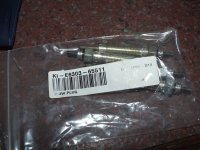
Pic 1: new glow plugs
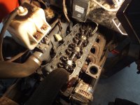
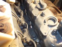
Pic 2: view of the valve train (muffler removed)
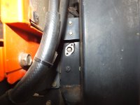
Pic 3: Timing mark inspection window
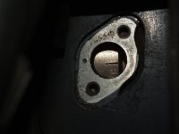
Pic 4: Close-up of timing marks aligned
Pic 5: New plugs installed
Cheers, Taz.
My DK45 is a 2002 model with the 4A220 engine.
Over the last few weeks I had noticed a gradual worsening in cold starts, with lots of smoke at start up persisting for a few seconds coupled with rough running. The engine would smooth out after several seconds with the smoke disappearing completely. With our weather slowly cooling off here in Tas (a few frosty mornings already), the problem was only going to get worse. Anyway, I had the opportunity to test the glow plugs with a multimeter. I tested them while still in the engine, with the busbar (the rail that connects all of the plugs together electrically) removed. The factory workshop manual states 0.8 ohms resistance value for the plugs. All but one returned satisfactory results. The offending glow plug showed an open circuit (presumably a broken coil inside). I was tempted to replace only the defective glow plug, but knowing that one had failed the others wouldn't be far behind. After all, they were all installed at the same time at the factory, and that was 950 hours ago. I also checked to make sure that the main power lead that powers the glow plugs was delivering full voltage, which also allowed me to see if the relay timer was working properly (I counted 15 sec total time). After ordering a full new set of plugs from a local dealer (at $60AU a piece - ouch
), I proceeded to tackle the job.My Daedong has a FEL attached and I wasn't bothered to remove it. It did make access more difficult but I'm not an old fart yet so I just put up with it :laughing: . Before attempting to crack the plugs loose I cleaned the area thoroughly with compressed air and sprayed the bases of the plugs with CRC. After removing the glow plug busbar I successfully cracked each glow plug loose (that was a relief
). I inspected the probes of each glow plug and all seemed to have the same appearance. Before installing the new plugs, I decided to check the valve clearances, as it looked to me that the valve cover had never been removed.Adjusting the valve clearances of course requires rotating the engine manually, and since the glow plugs were already out it was an ideal time to check the clearances. The engine was easy to turn over by simply pulling on the fan and belt simultaneously (being careful not to put too much gorilla force on the plastic fan blades
). I had to remove the muffler for better access and to later completely remove the valve cover. The four nuts securing the muffler came out easily after a quick spray with CRC and the valve cover nuts were easy to undo as well. The valve cover itself, however, needed careful separation from the cylinder head by the use of a thin scraper blade to 'break' the seal. Once the cover and seal had been removed, I inspected the seal, which looked to be in serviceable condition (still pliable and 'soft'). So I didn't bother buying a new one, instead giving it a careful clean up with cloth.Now, it took me a while to find the location of the timing marks. The workshop manual states that the marks are on the flywheel, but makes no reference to the location of the inspection 'window' (obviously at the rear of the engine but where exactly?). Eventually I found a little cover fasted by two bolts on the right side of the tractor (accelerator pedal side). The little cover has a cork gasket behind it, which can be damaged easily. After prying it off carefully, I found that I was only a couple of degrees off TDC compression stroke on No1 cylinder. I had already roughly located TDC compression stroke on No1 cylinder by rotating the engine clockwise (when view from the engine pulley) and waiting for the No4 cylinder valves to 'rock', meaning that the intake valve is just opening while the exhaust valve is just closing (if that makes sense :confused2: ). Anyway, once the timing marks were aligned I proceeded to check the valve clearances. Note that the engine must be stone cold for this procedure.
The values are:
0.25mm (0.010in) intake
0.30mm (0.012in) exhaust
With No1 cylinder on TDC compression, I measured the the clearances on:
Intake and exhaust on No1 cylinder
Intake on No2 cylinder
Exhaust on No3 cylinder
They were all on the loose side, but only just. After adjusting the above valves, I rotated the engine exactly one full turn clockwise (when viewed from the engine pulley). With the timing marks aligned again, I measured the clearances on:
Exhaust on No2 cylinder
Intake on No3 cylinder
Intake and exhaust on No4 cylinder
Again they were a tad on the loose side, so I adjusted them to spec. After checking to make sure all of the adjusting locking nuts were tight and that no feeler gauges or any other tools were left inside the engine, I cleaned the sealing surface on the cylinder head and reinstalled the valve cover, tightening the nuts progressively starting from the centre of the cover out to the ends. With the muffler back in, I lubed the threads of the new glow plugs with a small amount of anti-seize (cast iron cylinder head with steel glow plugs so hopefully no risk of electrolysis) and nipped them up firmly (but not too tight). With all of the other bits and pieces bolted back in it was time to kick the engine in the guts. On my DK45 the glow plug indicator on the dash lights up for 8 seconds, but I wait (listen) for the relay to click off (another 7 seconds) before cranking the engine. The difference in that cold start was well worth the time and money. The engine started instantly with only a quick small puff of smoke and not to mention it ran smoothly. It really did put a smile on my dial
.Below are some pics (hopefully they will be visible) that might help visualise things.
Pic 1: new glow plugs
Pic 2: view of the valve train (muffler removed)
Pic 3: Timing mark inspection window
Pic 4: Close-up of timing marks aligned
Pic 5: New plugs installed
Cheers, Taz.