Dump Truck Hydraulic Lines

   / Dump Truck Hydraulic Lines
  • Thread Starter
#11  
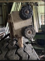
I attached a photo pointing to what someone told me was pressure relief on the valve body. The other pictures are the flow control valve that was removed.

How would I go about specifying the right pressure relief valve to add to the system

Many thanks!
 

Attachments

  • A2E72B1A-F691-4DB8-B4E7-AD7C57E37A80.jpeg
    A2E72B1A-F691-4DB8-B4E7-AD7C57E37A80.jpeg
    1.8 MB · Views: 67
  • 1E2F46AD-500B-47E8-A1CC-434D12D0114E.jpeg
    1E2F46AD-500B-47E8-A1CC-434D12D0114E.jpeg
    1.7 MB · Views: 186
  • E2F7127F-990E-4BC8-BE50-3A726A167ED8.jpeg
    E2F7127F-990E-4BC8-BE50-3A726A167ED8.jpeg
    2.3 MB · Views: 78
  • 0879DF4C-A70D-4B71-8F8B-8878869B6A27.jpeg
    0879DF4C-A70D-4B71-8F8B-8878869B6A27.jpeg
    2 MB · Views: 110
  • 33A78293-75C4-45AD-88CC-986F80E6B5F5.jpeg
    33A78293-75C4-45AD-88CC-986F80E6B5F5.jpeg
    1.6 MB · Views: 68
   / Dump Truck Hydraulic Lines #12  
It sounds like I should connect the power beyond outlet to the tank. When the dump bed isn't being used and the pump is running the power beyond will dump all the fluid into the tank. When I use the dump bed valve the power beyond will be cut off and flow to the dump cylinder. Is that correct?
Correct, that is the way it will work well.
The original setup provided a set flow to the control valves with the rest of the flow going to the spreader. When a control valve was not being used that valve flow was looped back into the system for the spreader. When the plow was actuated the sander would have slowed slightly but still ran from the dividers flow and picked back up after the valve was returned to center.
 
   / Dump Truck Hydraulic Lines #13  
Is that the diverter? Whatever it is, I've added an arrow pointing at the relief valve.
Relief valves are adjustable. They can be opened up. Inside will be seals plus some sort of compression spring-loaded poppet or ball bearing that seals an orfice. Adjustment for pressure at which it opens is done by changing the preload on the spring. Some springs have a threaded adjuster, others use shims.
Either way changes the preload and thereforenthe psi at which it opens.

Most Ag machines run at 3000 psi max, but not all do. Don't screw around with psi; and only use rated hydraulic fittings. Plumbing fittings will often thread on, but please DON'T.

For finding a proper psi, look at the markings on your hoses and hose fittings. Then call the manufacturer and ask what working pressure that part number is designed for. Set relief at that pressure +- 10%. Be real suspicious if anyone tells you higher than 3000 psi for a working pressure.

On dumping the PB line straight to the tank like LouNY says is OK. It might work. It all depends on how much of the flow in your valve was designed to go to the PB. It might work if the PB flow is smaller than the main, but won't if the PB flow was designed to handle full pump output.
No way to know, different valves had different schemes. But I agree with Lou that it won't hurt to try. At worst you will just not get enough pressure to lift a load and we can work on one of the other ideas.
Diverter?? showing relief valve.jpg
 
   / Dump Truck Hydraulic Lines
  • Thread Starter
#14  
That photo you added the arrow to is the flow control valve I removed.

The flow diverter is the square silver box still on the truck.

So it looks like the flow control valve I removed was acting as the relief for the the valve block and the flow control valve. Interesting. The return to tank hose on the flow control valve was a smaller size hose.

There are some "pipe" fittings still in the hydraulic connections. I removed more of them when removing stuff. And I'm guessing it was like that a long time. Not that it makes it ok, but it does seem that whatever pressure this system works at won't blow up those pieces immediately. But I understand shock loads and how things can happen to spike pressure.
 
   / Dump Truck Hydraulic Lines #15  
That photo you added the arrow to is the flow control valve I removed.

The flow diverter is the square silver box still on the truck.

So it looks like the flow control valve I removed was acting as the relief for the the valve block and the flow control valve. Interesting. The return to tank hose on the flow control valve was a smaller size hose.

There are some "pipe" fittings still in the hydraulic connections. I removed more of them when removing stuff. And I'm guessing it was like that a long time. Not that it makes it ok, but it does seem that whatever pressure this system works at won't blow up those pieces immediately. But I understand shock loads and how things can happen to spike pressure.
Yes, I'm sure the one I drew the arrow to is a relief valve. i didn't know which box it was on.

The one you are pointing to with your finger in the photo may be a relief valve. I've never seen one like that, but that means little. Kinda small, but It is on the main valve body and located where you would expect a relief valve to be on the valve body. Lets say it is a relief, and also there was a relief back on the flow control valve assembly. That makes the right number, and also puts them where they should be located in the circuit. Makes sense.

Are you going to try Lou's idea and just dump the PB to the sump? Whether that works or not .... and how well.... just depends on the geometry of the passages inside that particular main valve body. I don't see a down side other than the bed may have decent lift power for small loads but not much as the load increases. Reason for that is that flow tends to follow the easiest low resistance path - and that would be out the PB and to the sump. .
rScotty
 
Last edited:
   / Dump Truck Hydraulic Lines #16  
I'm not sure what you mean. I still need the hydraulic pump for the dump bed.
OK, I thought you were looking to remove it altogether. If you need pictures of my setup now that it’s done, I can send. I had a dump truck set up with hydraulic lines for bed auger, bed tilt & drop spinner
 
   / Dump Truck Hydraulic Lines
  • Thread Starter
#17  
I think the easiest solution is to put the flow control valve that I removed back where it was (but under the cab, not in it), and just have its return to tank connected. Block off the two lines it had feeding the auger and spreader. Then the system will effectively be back to how it was.
 
   / Dump Truck Hydraulic Lines #18  
I think the easiest solution is to put the flow control valve that I removed back where it was (but under the cab, not in it), and just have its return to tank connected. Block off the two lines it had feeding the auger and spreader. Then the system will effectively be back to how it was.

Yes, that would work. I wondered if we would come back to that.
In fact from message #10:

! One idea I just had is to put the auger & spreader control valve back into the circuit, but take off the handles and plug the cylinder ports so it cannot be actuated. Add a relief valve if it doesn't have one. (It does) Then you would have a place to put the PB line and also get back your original second return line. Also since the flow would be split, the original valves GPM rating is good. They can all handle their share of the flow.

rScotty
 
Last edited:

Tractor & Equipment Auctions

Cat Engine w/ Fuel Tank (A36338)
Cat Engine w/ Fuel...
Genie GS2646 Scissor Lift, (A35430)
Genie GS2646...
2014 Chevrolet Silverado Crew Cab Pickup, (A35430)
2014 Chevrolet...
Bluebird Engine Hoist (A34127)
Bluebird Engine...
Mitsubishi FG30K Industrial Forklift, (A35430)
Mitsubishi FG30K...
Volt 8 Gallon Air Compressor (A34127)
Volt 8 Gallon Air...
 
Top