TN75DA Cab wiring diagrams

   / TN75DA Cab wiring diagrams #1  

Harry in Ky

Veteran Member
Joined
Jan 27, 2012
Messages
1,562
Location
Winchester Ky
Tractor
Allis Chalmers ED 40
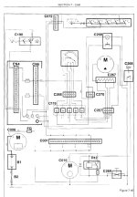
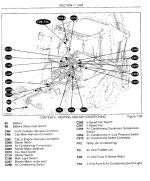
Does anyone have(or have access to) the cab wiring diagrams? I'm trying to trace the current path for the A/C clutch circuit. It appears to be a blue wire, probably about 22 ga. It appears to originate at the blower switch, passing through the A/C switch, most likely to/through the thermostat. From there the harness seems to go towards the right side of the cab, probably down the right post panel with the small fuse block and light switches. From there I assume it somehow makes it's way to the engine compartment and the compressor. It doesn't seem to have any path through the relay panel under the dash. At least I can find no continuity there with any wires from either end.
Short of removing the headliner, and half the cab's interior to follow the wire, a diagram at this point would be of great help in determining the path of the circuit, and what, if any, more components might be between the overhead switches and the pressure switch connector near the compressor.
 
   / TN75DA Cab wiring diagrams
  • Thread Starter
#2  
No takers yet?
 
   / TN75DA Cab wiring diagrams #3  
This may or may not help. It is from the manual for my 575E backhoe. It is not even correct for my tractor as far as component location but the general path of electrical components may help.

On mine there is a relay on the right side firewall under the hood. There should be a low pressure cutout switch on the receiver drier behind the grill that completes or opens the ground to the relay. It should open to prevent the compressor from running if the refrigerant charge gets too low. You can try turning it on and jump across the contacts on the switch on the drier for a second to see if the compressor clutch engages. If it does it's just low or out of freon. The easiest way to find the leak is charge it with some UV dye and look over it with a black light. Some things will glow that are not the dye but if it's glowing and oily you have found a leak.
 

Attachments

  • AC-wiring.jpg
    AC-wiring.jpg
    112.6 KB · Views: 16,350
  • AC-wiring-legend.jpg
    AC-wiring-legend.jpg
    148.5 KB · Views: 6,486
   / TN75DA Cab wiring diagrams
  • Thread Starter
#4  
Thanks, but I wasn't able to find any relays outside the cab. We're discussing two different tractors, so the diagrams wouldn't be the same. The pressure switch, clutch and related wiring are all working. Refrigerant level is not an issue. The problem here is to determine how the signal gets from the thermostat to the area outside the cab and into the engine compartment.
 
   / TN75DA Cab wiring diagrams #5  
Thanks, but I wasn't able to find any relays outside the cab. We're discussing two different tractors, so the diagrams wouldn't be the same. The pressure switch, clutch and related wiring are all working. Refrigerant level is not an issue. The problem here is to determine how the signal gets from the thermostat to the area outside the cab and into the engine compartment.

I don't understand why you want to know how the power gets to the clutch if "The pressure switch, clutch and related wiring are all working".

Regardless of what tractor you have a 22ga wire is not large enough for the current draw of an AC clutch. The clutch will be fed by a larger gauge wire from a relay. The 22ga wire can supply power to a relay. They don't want the AC running unless the fan is on so it starts at the fan switch. If you have an AC on/off switch it will go from the fan switch to that and then to the thermostat. The signal from the thermostat will go to the relay where ever it is located. The low pressure switch on the receiver drier will complete the ground to the relay. If everything is in fact "all working" you can turn the key on, turn the blower on low, and have someone turn the AC switch on and off. You should be able to hear the relay click to try and track it down.

It could be done without a relay but it would require a larger gauge wire to the clutch. Most systems work through a relay.

I recently went through getting the AC working on my tractor. Someone had bypassed the relay, left the compressor off, and generally made a mess of things. I wasn't able to find the entire path of the wire going to the relay but found the relay with the method described above. I ripped all the added on wiring out and hooked everything up to factory locations and it all worked so I had no further need to find the path. For what it's worth my relay was tucked out of sight in the engine compartment against the firewall.

Good luck with your endeavor.
 
   / TN75DA Cab wiring diagrams #6  
There are relays in the RH 'B' pillar that relate to the A/C circuit IIRC and a maxifuse near the clutch pedal for certain.
 
   / TN75DA Cab wiring diagrams
  • Thread Starter
#7  
Yes there are six or eight fuses in the cab pillar along with some switches for various lights, I guess, but no relays I'm aware of. Haven't removed the pillar yet to prove that. I have searched the parts diagrams and thus far have found nothing in the way of a dedicated A/C relay. I assumed there would be one, I just don't know where else to look for it. For the moment I have added in a relay to supply battery voltage to the compressor clutch, and ran an external wire from what I believe to be the thermostat output(can't tell for sure without either a wiring diagram or taking down the headliner and opening up the air conditioner unit). Ran this wire out the door and under the hood to power said relay. This seems to be working, and should survive for a few days until I can get the circuit figured out.
 
   / TN75DA Cab wiring diagrams #8  
Well you should remove the pillar cover; you might be surprised. As stated, a 22ga wire isn't powering the compressor clutch.
 
 
Top