Thoughts on this used welder?

   / Thoughts on this used welder?
  • Thread Starter
#101  
your dc welds are cold.weld a few passes with the dc turned all the way up.then swap the cables and try a few more.post them and let me look . also clean your welding plugs.i use a car battery brush.check your 220 receptacle and make sure it has enough voltage.

Yup. Cold is exactly what I was thinking when the metal was beading up. Molten metal flows to the heat, so if it is beading up it means that the work piece is not getting enough heat. For what it's worth, I tried turning the welder all the way to its hottest setting, and the results were the same, so I don't think that's the issue. I have also checked the output of the receptacle, and it's dead-on 240.
 
   / Thoughts on this used welder? #102  
Post some pictures of the diodes so we can reference the style and maybe a part #.
 
   / Thoughts on this used welder? #103  
When I first started to bubblegum metal on metal, I bought a too small unit. it was a bear to strike and arc.
Got a bigger unit, but had no power supply.
bought an engine driven one.... lower powered but laid a beautiful bead (for me anyways) until the rod came out the side of the engine.
finally got proper power, and started using the 220 unit. AC only....

here is what I learned as a NOOB!
1) listen to the experienced guys
2) read on proper rods, and use only those to learn on
3) clean the metal well. I like an angle grinder with a brush AND and angle grinder with a sanding wheel AND an angle grinder with a grinding wheel (Yes, I have all three handy.... Learning is easier when you have everything you need handy)
4) play with the lowest settings that will give you nice welds... easy to burn using higher power. Technique reallly develops when you force yourself to pay attention to speed, distance etc...
5) Clean the metal well.
6) Clean the metal well.
7) Auto darkening helmets are GREAT... but don't work well in bright sunshine. Set up a shade of some sort.
8) Welding can be a lot of fun, And VERY useful!

Hope you get the bugs worked out of the DC.
I don't have one, but borrow a Miller Dialarc, and an engine driven straight DC once in awhile, and know DC is nice.
I LOVE the engine driven welder!
 
   / Thoughts on this used welder?
  • Thread Starter
#104  
Post some pictures of the diodes so we can reference the style and maybe a part #.

The diodes are labeled IR 70HF30, and then on the other side, 80 32. A little google searching turns up this thread on WeldingWeb. The innards of that welder look identical to mine and the label on the diodes matches.

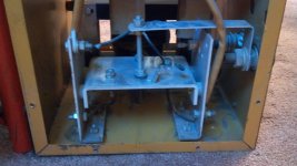
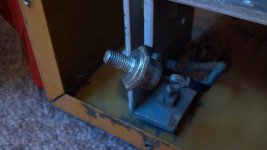
Photos below show my entire rectifier array, and then a single diode.

2012-09-23 14.21.17.jpg2012-09-23 14.18.03.jpg

Looks like that WedldingWeb thread has links to replacements. That may be my next step. I'm a little befuddled because the diode test function on my multimeter shows a "correct" value of about 4-5 volts for the diodes, but the resistance function shows 2-4 Mega-ohms, which my understanding is should be treated as an open. I don't know how to resolve that. If I had to jump right this minute, I would say, "Well, it doesn't weld right on DC. We know the AC transformer is good. What else could it be than the diodes?" It looks like there is an additional transformer as part of the DC circuitry. Is there some way I can test that? What other tests could narrow down the problem before I just pull out my wallet and cross my fingers?
 
   / Thoughts on this used welder? #105  
The diodes are labeled IR 70HF30, and then on the other side, 80 32. A little google searching turns up this thread on WeldingWeb. The innards of that welder look identical to mine and the label on the diodes matches.

Photos below show my entire rectifier array, and then a single diode.

View attachment 281870View attachment 281873

Looks like that WedldingWeb thread has links to replacements. That may be my next step. I'm a little befuddled because the diode test function on my multimeter shows a "correct" value of about 4-5 volts for the diodes, but the resistance function shows 2-4 Mega-ohms, which my understanding is should be treated as an open. I don't know how to resolve that. If I had to jump right this minute, I would say, "Well, it doesn't weld right on DC. We know the AC transformer is good. What else could it be than the diodes?" It looks like there is an additional transformer as part of the DC circuitry. Is there some way I can test that? What other tests could narrow down the problem before I just pull out my wallet and cross my fingers?

Joshua, that "other transformer" is likely just a choke. In other words a coil with a iron core. An inductor.. Should just have 2 leads.. and they should have a very low resistance, maybe an ohm or less. I would check the diodes by un-soldering one connection to each of them and make sure they conduct one direction (low resistance)and reverse the leads and they should look open. I always use an analog meter, for checking semi-conductors, less confusing that way. I would use the Rx100 scale. Part of being a good diagnostic tech is being totally familiar with your equipment and from checking hundreds of diodes and transistors, knowing exactly what a defective one and what a good one look like on the meter. Easy for me to say, having checked thousands of semiconductors. But if you do have some known good silicon diodes, you could compare them to your International Rectifier 70HF30 diodes to be sure before you invest in new ones. Have you found a schematic for the unit, to verify for sure that this other device is a choke? Hopefully we can get this machine going again and get you some welding practice.

70HF30 - SOLID STATE - DO5 70 Amp Silicon Rectfier | Newark


James K0UA
 
   / Thoughts on this used welder?
  • Thread Starter
#106  
Joshua, that "other transformer" is likely just a choke. In other words a coil with a iron core. An inductor.. Should just have 2 leads.. and they should have a very low resistance, maybe an ohm or less.

I think you're right about that. I will double-check, but I think you're right.

I would check the diodes by un-soldering one connection to each of them

Since the diodes are soldered on on side and bolted on the other, can I just un-bolt the "bolt" side and avoid desoldering? Or do I need to completely disassemble the diode from the array?

Easy for me to say, having checked thousands of semiconductors. But if you do have some known good silicon diodes, you could compare them to your International Rectifier 70HF30 diodes to be sure before you invest in new ones.

Coincidentally, I just a few months ago had to replace the rectifier on a motorcycle, which is basically the exact same thing we're doing here, so I have some idea what a good diode should look like. In that case, though, they gave a specific voltage range that the diode should read on the diode test function of the multimeter. Here, we only have nominal values to go off of. In my previous test, I found the following:

The rectifier bridge has four diodes as near as I can tell. Two of them show 3.3 MOhms through them and 0.44 volts drop using the multimeter's diode test function. The other two show 2.5 MOhms and 0.41 volts drop.

That was with the diodes connected to the array. I un-screwed the nut from one of the diodes and half-way disconnected it from the array (would have to desolder to do the other side) and verified that the result was the same. If I need to desolder the diode and test it on the bench, I can do that too.

Have you found a schematic for the unit, to verify for sure that this other device is a choke? Hopefully we can get this machine going again and get you some welding practice.

No schematic at this time.


Yup--that's the one. Too bad I have to order 100 of them! I found a diode that someone suggested as a suitable replacement. Only difference is that it is 70HF40--400 volts, not 300. I assume that only means it's a bit more rugged and would still be okay.

I wonder if I could increase the reliability of my welder by putting in higher-amperage diodes. Would that be worth considering? It really seems like they are the weak link in the DC duty cycle. They overheat and die, as diodes always do when you overheat them.
 
   / Thoughts on this used welder? #107  
I think you're right about that. I will double-check, but I think you're right.


Since the diodes are soldered on on side and bolted on the other, can I just un-bolt the "bolt" side and avoid desoldering? Or do I need to completely disassemble the diode from the array?


Coincidentally, I just a few months ago had to replace the rectifier on a motorcycle, which is basically the exact same thing we're doing here, so I have some idea what a good diode should look like. In that case, though, they gave a specific voltage range that the diode should read on the diode test function of the multimeter. Here, we only have nominal values to go off of. In my previous test, I found the following:


That was with the diodes connected to the array. I un-screwed the nut from one of the diodes and half-way disconnected it from the array (would have to desolder to do the other side) and verified that the result was the same. If I need to desolder the diode and test it on the bench, I can do that too.


No schematic at this time.


Yup--that's the one. Too bad I have to order 100 of them! I found a diode that someone suggested as a suitable replacement. Only difference is that it is 70HF40--400 volts, not 300. I assume that only means it's a bit more rugged and would still be okay.

I wonder if I could increase the reliability of my welder by putting in higher-amperage diodes. Would that be worth considering? It really seems like they are the weak link in the DC duty cycle. They overheat and die, as diodes always do when you overheat them.

Just the unbolting should be fine for the ohm test. The higher voltage rating will be fine.. In fact more than fine.. better,, as well as a higher current rating would be good. But first lets ascertain for sure that the diodes are in fact defective. They are most likely the culprit, but we need to know for sure.

James K0UA
 
   / Thoughts on this used welder? #108  
Joshua, one thing you could do if you want to rig up a "testbed" is get a 12 volt battery or 12 volt power supply, and at least a #57 lamp (typical old fashioned taillight) or a headlight from an old car, and put the diode in series with the circuit. One direction the lamp does not light at all. the other the lamp lights to near full brilliance (slight voltage drop). Just an idea, should not take too long to set up if you have these things. But this would test these diodes under a little bit of a load.

James K0UA
 
   / Thoughts on this used welder?
  • Thread Starter
#109  
Joshua, one thing you could do if you want to rig up a "testbed" is get a 12 volt battery or 12 volt power supply, and at least a #57 lamp (typical old fashioned taillight) or a headlight from an old car, and put the diode in series with the circuit. One direction the lamp does not light at all. the other the lamp lights to near full brilliance (slight voltage drop). Just an idea, should not take too long to set up if you have these things. But this would test these diodes under a little bit of a load.

Okay. Well, I've got good news. I did as you suggested with a tail-light and a 12 volt battery. I disconnected the post-end of each diode from the array and ran the bulb through it, then used the diode-check function of my multimeter. The results were different! Three of the diodes, the tester showed 0.702 volts. The third one, it showed 0.695. As I understand it, that's dead-on right for silicon diodes. I also checked the resistance of the diodes while the 12 volt bulb was running, and they showed 0.00 ohms. This seems to indicate that all the diodes are working correctly.

I also ran the bulb through the whole rectifier array, with the hot lead clamped on the wire leading into the array and the negative lead plugged into the + lug on the welder, and the bulb lit up brightly.

So... where does that leave us?!
 
   / Thoughts on this used welder? #110  
Okay. Well, I've got good news. I did as you suggested with a tail-light and a 12 volt battery. I disconnected the post-end of each diode from the array and ran the bulb through it, then used the diode-check function of my multimeter. The results were different! Three of the diodes, the tester showed 0.702 volts. The third one, it showed 0.695. As I understand it, that's dead-on right for silicon diodes. I also checked the resistance of the diodes while the 12 volt bulb was running, and they showed 0.00 ohms. This seems to indicate that all the diodes are working correctly.

I also ran the bulb through the whole rectifier array, with the hot lead clamped on the wire leading into the array and the negative lead plugged into the + lug on the welder, and the bulb lit up brightly.

So... where does that leave us?!
So basically the current will only go thru the diode in one direction and not the other, that's important.
The voltage drop across the diode looks good. They usually fail by shorting or open circuit. Open would have full voltage drop across it in either direction and short would be no or very little drop. Sometimes, as James, alluded to, they will appear to be ok until a decent amount of current is passing.
 
 
Top