Thoughts on this used welder?

   / Thoughts on this used welder? #171  
joshuabardwell said:
I think I see what you're getting at. But will the loss in power translate to a drop in voltage?
Yup. You want the voltage drop to be in the arc. Electrode at 25 volts, workpiece at 0 volts. Any additional voltage drop is not wanted.
Or would I need something that measures current, like an amp clamp? Current = Volts / Resistance, right? So if resistance goes up somewhere in the circuit, current will drop while voltage will remain constant. No?
Sort of. In a good welding circuit, most of the 25 volts will be across the arc, and very little in the wireing, diodes, choke, connections.

In a poor circuit, you might have 25 volts across the arc, and 5 volts accross a bad connection. Or worse two bad connections ( 10 volts).
That will reduce the amount of current flowing in the circuit.

FYI, the current will be the same in any point circuit, at any one moment. Those electrons arn't pileing up anywhere. :)
 
   / Thoughts on this used welder?
  • Thread Starter
#172  
FYI, the current will be the same in any point circuit, at any one moment. Those electrons arn't pileing up anywhere. :)
Yes, of course. See--this is where my lack of theoretical background shows. I have a lot of practical experience troubleshooting things, and if I really sit down and think about it, I know just a little bit of theory, but I tend to forget it.

Well, I'm game. I'll pull out the volt-meter and go. How about an incandescent light bulb as the load? Why heck! I have one right here! Lemme just put on my welding gloves before I go sticking my hands into the live welder, though. They're good up to 400 volts, right?
 
   / Thoughts on this used welder? #173  
joshuabardwell said:
Lemme just put on my welding gloves before I go sticking my hands into the live welder, though. They're good up to 400 volts, right?

Maybe, if they are dry. Stay away from the input side of the transformer, and power switch, etc.

Thats all for me, gotta go to bed, its 12:30 here.
 
   / Thoughts on this used welder?
  • Thread Starter
#174  
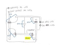
Okay, CNCDan. Here's what I've got:

Welder Voltage.jpg

Everything that's not marked was between 0 and 1 mV. I also didn't do any measurements from the lugs out the leads to the load because of the clean 27 volts measured between the lugs, which is what was expected.

Now I'm not enough of an electrical engineer to make total sense out of all this, but one thing I do notice is that two of the diodes on one side of the circuit are at 27 volts, and the two diodes on the other side of the circuit are at 3.7 volts and 80 mV. One of these things is not like the other. Seems like the voltage across the diodes on the same side of the circuit ought to be the same. But I don't know. What do you think?
 
   / Thoughts on this used welder?
  • Thread Starter
#175  
By the way, this is kind of funny. I knew that I wanted a solid connection to the light bulb's base, so I cut open a spare computer power cable that I had laying around and meticulously soldered it to the bulb's base. My soldering iron is kind of cheap and weak, so it took ten minutes or so. As I was clamping the stinger to the cord, I realized that I probably could have just stuck the stub of a used rod to the light bulb's base and accomplished the same thing with a lot less trouble. Well, it was funny to me anyway.
 
   / Thoughts on this used welder? #176  
Joshua have you checked that capacitor? do you have a cap check function in your digital multimeter. If not do you have an analog VOM. You can check a cap by isolating the capacitor, then putting the leads of an analog ohm meter on the cap and watching for a "kick" of the meter and then reversing the leads and watching the kick again.. If you see any thing but an open after the kick.. in other words a leakage so that it is showing a resistance all the time then the cap is "leaky" if it does not kick at all or the kick is too weak for its rated value then the cap is bad.. Now you are probably wondering how to make a subjective judgement from what I have described.. This is the difficult part. You either have lots of experience checking caps using this method, and you know about how much the kick should be or you compare the deflection of the meter (kick) with a known good cap of the same value. You also have to be on the correct Ohms range on the VOM, usually RX100. I know this may sound confusing, and it can be, but I have checked hundreds of caps using this method, but it is a subjective test. A good analog VOM is better for checking caps and diodes and any kind of dynamic measuring, like measuring varying voltages while tuning up stages in a radio. A digital meter is more precise for all measurements. You really need both..

James K0UA
 
   / Thoughts on this used welder?
  • Thread Starter
#177  
Joshua have you checked that capacitor?

With the welder un-plugged, I shorted the leads on the cap with the multimeter probe and watched the voltage trickle down to zero. The voltage was very low to begin with, so I suspect the cap was mostly discharged already. I suppose that would qualify as a "no" to your question. :D I haven't checked it in any meaningful sense.

do you have a cap check function in your digital multimeter. If not do you have an analog VOM.

Nope, and nope.

You can check a cap by isolating the capacitor, then putting the leads of an analog ohm meter on the cap and watching for a "kick" of the meter and then reversing the leads and watching the kick again.. If you see any thing but an open after the kick.. in other words a leakage so that it is showing a resistance all the time then the cap is "leaky" if it does not kick at all or the kick is too weak for its rated value then the cap is bad..

Can this test be performed with a digital meter? What should the starting condition of the capacitor be: charged or discharged? Should the circuit be powered at the time the test is performed?

You also have to be on the correct Ohms range on the VOM, usually RX100.

I do have both an auto-ranging and a non-auto-ranging digital multimeter, but not an analog.

Joshua
 
   / Thoughts on this used welder?
  • Thread Starter
#178  
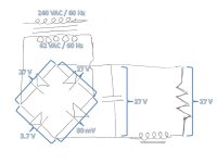
I did a little more studying, and I believe that I have translated the welder's circuitry to a proper electrical schematic. I tested the diodes and they're all the same polarity, so that will make replacing them easier if it comes to that. I'm posting the schematic here just for the sake of documentation. I wish I knew somebody who had the electrical background to look at this and tell me if it basically seems correct or not. I know there's somebody out there for whom it would be a piece of cake, but I don't know who they are or how to get a hold of them. Maybe I should post the schematic under a separate subject line to catch people for whom this thread has lost interest.

Welder Voltage Schematic.jpg

James: here is the result of the capacitor test you suggested. What I did was turn the welder on for about five seconds (with the light bulb in circuit as a load) to charge the capacitor and then turn it off and put the multimeter across the leads of the capacitor with the Ohms function selected. I did the test twice, reversing the leads between the two tests. Instead of trying to describe the results to you, I just took a video.


BTW, you said to "isolate the cap," which I'm not sure if you meant I had to remove it entirely from the circuit. If so, then this test is invalid, as I did not do that.
 
Last edited:
   / Thoughts on this used welder? #179  
joshuabardwell said:
I did a little more studying, and I believe that I have translated the welder's circuitry to a proper electrical schematic. I tested the diodes and they're all the same polarity, so that will make replacing them easier if it comes to that. I'm posting the schematic here just for the sake of documentation. I wish I knew somebody who had the electrical background to look at this and tell me if it basically seems correct or not.
It is correct.

What you have is a very basic power supply that is used in many electronic devices. Just that this one is bigger than most. The transformer steps down the voltage, and increases the current. It also is designed to limit current. The four diodes in a bridge configuration rectify the AC output. The capacitor is like a battery and can store and supply a little current. It averages the highs and lows of the rectified DC current. The choke acts as a flywheel an keep the current more even.
 
   / Thoughts on this used welder?
  • Thread Starter
#180  
I appreciate the validation of the schematic, Dan. Any opinion on the voltage across the diodes? Specifically the fact that two of them are at 27 volts, while the other two are at 3.7 volts and 80 mV? I have no idea how to analyze the circuit, but I can play the old game of, "one of these things is not like the other."
 
 
Top