Ford 3600 Instrument Panel Wiring

   / Ford 3600 Instrument Panel Wiring #1  

TNSuperC

Bronze Member
Joined
Apr 4, 2011
Messages
66
Tractor
Farmall Super C, Ford 3600
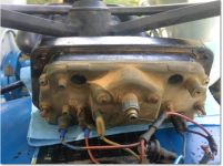
I have a 1977 3600 that is in need of re-wiring. I have the Ford Repair Manual. The schematic shows a voltage stabilizer in between the key switch and the fuel gauge. The manual says this is required to keep a steady 10V output for the fuel and temp gauges. My Instrument panel does not have this device. Does anyone have a photo of the back of this panel showing where the voltage stabilizer is mounted? Here are photos of my panel front and back. What a mess!
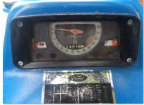
Instrument_Panel_Front.PNG

Instrument_Panel_Rear.PNG
 
   / Ford 3600 Instrument Panel Wiring #2  
Your proofmeter does not use a voltage stabilizer. X600 tractors had a change in mid-production that changed the cluster from tach swinging right to left to one swinging left to right. The later one uses no stabilizer and different senders for temperature and possibly fuel. Keyed power comes in to one gauge and is bridged to the other. Black is ground. Green goes from S post on fuel gauge to fuel sender. Another wire goes from S terminal of temp gauge to the temp sender. Idiot lamps and backlighting sockets plug into the assembly in the appropriate locations.
 
   / Ford 3600 Instrument Panel Wiring
  • Thread Starter
#3  
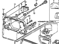
Thanks RickB, I need to study this a bit. I've attached a drawing from the Alma Ford New Holland parts site. Part #8 is the voltage stabilizer.
Ford_Site_Cluster_Drawing.PNG
 
   / Ford 3600 Instrument Panel Wiring #4  
Thanks RickB, I need to study this a bit. I've attached a drawing from the Alma Ford New Holland parts site. Part #8 is the voltage stabilizer.
View attachment 438164


That's great, it's just not your proofmeter. Note the tach needle resting to the right.
What is the unit code of your tractor?
 
   / Ford 3600 Instrument Panel Wiring
  • Thread Starter
#5  
That's great, it's just not your proofmeter. Note the tach needle resting to the right.
What is the unit code of your tractor?

Yes, thanks for pointing that out to me. Guess, I'll run the wire directly to the Fuel Gauge like you already said and see what happens. My unit code is 7M12B.
 
   / Ford 3600 Instrument Panel Wiring #6  
Interesting that your unit code indicates late 1977 production but the proofmeter you have was put in service in mid 1979. Perhaps it is a replacement and the senders were changed to match.
In any event, power to the voltage stabilizer would come directly from the accessory feed (chassis harness) then output from the stabilizer would power the temp and fuel gauges. Leads from the gauges would run directly to the respective senders, temperature via the rear main and front main harnesses, and fuel via a single green wire a foot or so long.
 
   / Ford 3600 Instrument Panel Wiring
  • Thread Starter
#7  
I guess you can't count on em havin what they're supposed to. Would you happen to know the electrical characteristics of the older vs newer fuel sending units?
 
   / Ford 3600 Instrument Panel Wiring
  • Thread Starter
#9  
Using a Fluke 87 DVM, I get 332 Ohms when the tank is ~>3/4 full. The sending unit is marked with "AC" and "Made in England."
I've tested my connections without the voltage stabilizer in the loop. The temp gauge moves but the fuel gauge remains in its position.
I used the "red with green stripe" wire coming from the 3A fuse to power the two gauges. This wire is hot with ~12.67V when I turn the ignition to the first position. After the tractor is started, the voltage climbs to ~14.67V.

A characteristic I noted when I first turned the ignition switch to the first position is that the temp gauge moved towards the "red zone" on the right side of the gauge but then moved back towards the left side a bit after the tractor was running.
I will run it for a while with this wiring to see if the temp gauge "acts right."

I took a resistance reading across the fuel and temp gauges. They both show ~50-60 Ohms which seems reasonable. The fuel gauge could just be stuck.
 
 
Top