sd455dan
Super Member
- Joined
- Oct 23, 2012
- Messages
- 5,203
- Location
- North Idaho
- Tractor
- Rhino 554, Ford 550 TLB (JD X500, MTD, Gilson riding mowers) Ford 3000-Sold
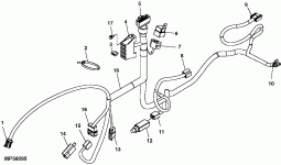
That is what I posted and then removed because of the earlier statement that Hot wiring the clutch connector did engage the clutch-
This is key because it is not clear to me whether the connector was still connected or was removed and +12vdc AND Ground was applied.
If the connector was removed when the clutch was (hot wired) and both ground and power were both connected to battery + and -
And the linked diagram is in fact correct...
I would suspect a failed ground circuit from the clutch connector to the referenced schematic nodal ground point.
edit: Need more information from OP on exactly how the hot wiring clutch test was done.
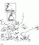