Aussiebushman
Gold Member
- Joined
- Jul 31, 2008
- Messages
- 251
- Tractor
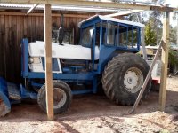
- Ford 6000
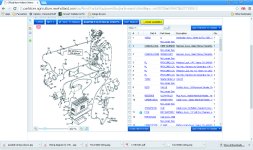
OK. I give up and need help. This all began when I decided to fix the non-working fuel /temp gauges and ammeter warning light. so I pulled off the covers and found the mess of wiring "repaired" by the last owner. Many wires were bare, some simply disconnected and it is a wonder the machine started and ran without catching fire. Please consider and comment:
The IT shop manual does not have a section on wiring or instruments
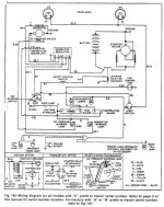
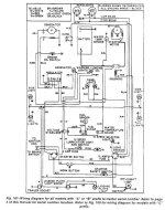
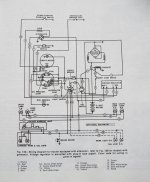
The Internet has any number of wiring diagrams and two thes are included in this post. But - neither of these has much resemblance to what it actually installed. My tractor is presumably a US model (not Euro) but the Australian distributors may have modified the wiring.
The schematic from ALMA (see picture) is as close as it gets but no wiring colors are shown so it is not very helpful in terms of rewiring
PLEASE - anyone with a correct wiring schematic for a 6000 model - please supply me with one
This is what we now have:
I guess in the final analysis, I can just put it all back together and hope but that will not fix the instrument problem. Any assistance most welcome.
Alan
The IT shop manual does not have a section on wiring or instruments
The Internet has any number of wiring diagrams and two thes are included in this post. But - neither of these has much resemblance to what it actually installed. My tractor is presumably a US model (not Euro) but the Australian distributors may have modified the wiring.
The schematic from ALMA (see picture) is as close as it gets but no wiring colors are shown so it is not very helpful in terms of rewiring
PLEASE - anyone with a correct wiring schematic for a 6000 model - please supply me with one
This is what we now have:
- There was NO power to the instrument cluster so lots of damaged wiring has been replaced with soldered/heatshrink joins to replace the previous dodgy versions. (Yet to be reconnected to the battery until I resolve the issues listed here)
- There are red and green wires coming from the instrument cluster but they are not connected to anything, An ohmmeter shows connectivity with the yellow/red wires at the instrument panel but the green wire has no connectivity. I should think these should go to the ignition switch but can't see any spare or missing terminal contacts. Also an orange wire is hanging out of the loom, but I cannot find anywhere this might go. Any suggestions?
- Instrument cluster has been removed, cleaned but not bench tested (auto electrician did not want to do it) I now have a replacement cluster out of an old car that should work if it is the present on that has failed.
- The 3 pin (plus ground) voltage regulator (NOT a 4 pin as shown in the diagrams) ditto. There are no breaks in the wiring and the unit looks OK
- The "inverter" has NOT been removed - it looks dirty but otherwise OK. I have no ideal what this unit does
- Sender units have NOT been removed - I doubt thee are the problem - one might fail, but not all at once so it is surely a power/connection issue
I guess in the final analysis, I can just put it all back together and hope but that will not fix the instrument problem. Any assistance most welcome.
Alan