Hydraulic Remotes...Again!

   / Hydraulic Remotes...Again! #11  
Reguy
If your system has a fixed displacement gear pump then Yes you can install a selector / diverter style in the pressure line before your FEL valve but you must also have a relief valve and tank line for the relief to protect the pump.

Have you checked your operating pressure on your tractor? With a fixed displacement pump oil is going somewhere. Smaller quick disconnect just increase the pressure drop they will only restrict flow once you get to the relief valve setting but not before that. Same with smaller hoses.

Does your tractor require installing a plug in a block before the FEL valve to divert the oil to the FEL? If yes The seals on this plug could be leaking allowing oil to bypass the FEL valve a couple of members have recently experienced this problem
 
   / Hydraulic Remotes...Again! #12  
When attaching my grapple I had to change the quick disconnects from the skid steer type 1/2” to a 3/8” 7241-1b type.

Found it interesting that all FEL lines (and third function lines) were 3/8ths while all 3 rear remotes were fed with 1/2” and equipped with 1/2 qd.
 
   / Hydraulic Remotes...Again! #13  
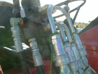
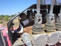
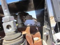
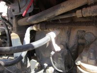
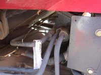
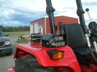
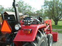
Here are a few photos of the triple rear remotes I had the dealer install on my new 2008 Mahindra 5525 when I bought it. Dealer's design. $750.


DSCF0138 (Medium).JPG

The connection to the power beyond (PB) port on the side of the FEL joystick block .

IMG_3886 (Medium).JPG

The output (return) line from the triple remote valve block (white tag).

IMG_3887 (Medium).JPG

The input line to the triple remote valve block from the PB port (white tag).

IMG_3888 (Medium).JPG

The return line from the triple remote valve block connection to the hydraulic reservoir (white tag).

IMG_3889 (Medium).JPG

The connection to the reservoir (white tag)

Remotes 5525-1.JPG

The triple control valve block for the remotes.


Remotes 5525-2.JPG

The three pairs of quick disconnects for the rear remotes.

Hope this helps.

Good luck
 
   / Hydraulic Remotes...Again! #14  
.... Back to my question. Does it seem reasonable to interrupt the pressure line to FEL valve, install a hydraulic manifold , then take outputs from the manifold to the FEL valve and to the the log splitter (or whatever is plugged into that output)? ....
In part the answer to that question depends on your answer to a previous question: How many lines does your current FEL control valve have?

From looking at Branson parts, loader and tractor manuals I found on a Branson Dealer website in Austrailia I'm almost certain you will find you have:
4 each - hoses to the FEL cylinders ('working ports')
1 each - pressure feed from tractor to the FEL valve ('P' port)
1 each - power beyond back to the tractor ('PB' port)
1 each - relief flow back to the tractor tank (the right side of transmission case) ('T' port)
TOTAL - 7 lines connected to your FEL control valve

IF that is correct, you have a constant-flow hydraulic system and your FEL control valve is the open/tandem-center type and already has Power Beyond capability.

______
IF that is correct and you insist on the 'manifold approach' then the manifolds (yes, multiple manifolds, keep reading) must be a selector-type where you select which control valve is in-use (one at a time only) and it must incorporate a relief valve with return to the tractors tank as described by oldnslo in his post above.

Why all of that? Because:
1. If you install an 'open' manifold where fluid can flow to either control valve all the time, then the fluid will always flow to the 'other' valve when you try to operate one, passing freely through the 'other valve' open center. No working port will get anything near operating pressure.
2. If you install a selector-type manifold (use either/or control valve but not both simultaneously) to avoid problem 1, then you can easily 'deadhead' your tractor pump during switchover which will cause instant over-pressure and destruction of the 'something' that has to 'give' when that happens (pump casing, pump drive coupler, a pressure pipe .... whatever is the weakest link and it won't be good, may be dangerous to the operator, will be expensive to fix).
3. Problem 2 can only be avoided by the added complexity of a manifold pressure relief valve and return hose to the tractor tank - that's the 'bypass' to avoid damaging deadhead during switchover of the manifold selector.

Why multiple manifolds? Because:
4. You have to address not only the 'P' pressure feed to each control valve, you also have to address the 'PB' pressure feed back to the tractor for each of those separate control valves. There's also the multiple low-pressure 'T' returns to tank/transmission that'll have to be addressed, but those can be an 'open' junction.

^^That's all a very complex approach, fraught with risk if the switchover of both 'P' and 'PB' isn't coordinated, a PITA to juggle all the manual switchover stuff, that's why ....
.... I have not heard of this solution before ....

_______

IMHO the "proper" and "safe" solution, the KISS solution intended and traditionally used for a system design like yours (and many other CUT's) for good reason:
  • Install correct open/tandem center control valves with 'PB' and 'T' ports/hoses (which is what your FEL control valve already is) in series for any/all aux implement controls.
  • In order to ensure delivery of the full ~8.x GPM that your tractor pump is capable of, all of the 'P' and 'PB' lines and fitting in that series-path should be 1/2" (#8) as previously stated by Brian (even if the implement itself uses a smaller hose/fitting at the working port connection).
Note that all of these same control valve-type and hose/fitting size rules apply even with the 'manifold approach'.

The "proper" solution is fully passive - you can use whatever external implement at-will with no manual switching of anything and it serves for lot's more other common and convenient rear-aux implements than just a static log-splitter (e.g. bucket grapple, hyd top link, etc, the list is endless when you have a rear aux that's 'conventional').

So why would one choose the 'manifold approach' which does nothing but add parts (more cost), complexity and the inconvenience of 'only-one-or-the-other-selection' when compared to the 'traditional' solution?
 
Last edited:
   / Hydraulic Remotes...Again! #15  
TX
Very nice explanation on adding valves in a fixed displacement pump circuit.

Reguy
None of this addresses the current issue of where is the flow going on your present system.
 
   / Hydraulic Remotes...Again! #16  
Reguy
None of this addresses the current issue of where is the flow going on your present system.
Absolutely agree.

Reguy .... Does your tractor require installing a plug in a block before the FEL valve to divert the oil to the FEL? If yes The seals on this plug could be leaking allowing oil to bypass the FEL valve a couple of members have recently experienced this problem
FYI from review of the Branson docs I found they do not use an internal plug in a divider block (as does my Yanmar, for example). Instead, they show that without an external valve installed, the divider block with 'always hot' P & PB ports has an external "U" assembly connecting those two ports installed outside the divider block; that external "U" assembly is removed to allow connection of the P and PB lines when an external valve is installed. KISS and effective approach, IMHO.

Unfortunately, all the docs I found use proprietary PNs for the fitting references .... I found no indication of the P & PB port sizes at the tractor divider block or the Branson FEL control valve for the external connections. One would hope they are nominal 1/2" flow ID / SAE #8 but who knows other than Reguy and his mic (?)

Reguy, if you want to determine any of your line fittings sizes, this might be of help:
http://www.discounthydraulichose.com/v/vspfiles/downloadables/thread_guide.pdf
https://www.discounthydraulichose.com/v/vspfiles/downloadables/qd_sizechart.pdf
 
Last edited:
   / Hydraulic Remotes...Again! #17  
Smaller quick disconnect just increase the pressure drop they will only restrict flow once you get to the relief valve setting but not before that. Same with smaller hoses.

That doesn't sound right but maybe it is. Putting a restrictor in the line will reduce flow but I realize there are other fluid dynamics at work. Can you elaborate?
 
   / Hydraulic Remotes...Again! #18  
Smaller quick disconnect just increase the pressure drop they will only restrict flow once you get to the relief valve setting but not before that. Same with smaller hoses.

That doesn't sound right but maybe it is. Putting a restrictor in the line will reduce flow but I realize there are other fluid dynamics at work. Can you elaborate?

npalen,
On systems with a fixed displacement pump (gear pump) the flow must go somewhere. On simple systems like those used on small tractors the oil typically flows through the FEL valve, to the 3 PH and then to tank. When any restriction or load exceeds the relief valve setting flow is then bypassed to tank through the relief valve.

If a pressure gauge, flow meter & flow restrictor are installed in the power beyond line you could watch the pressure climb as the the flow restrictor is closed but the flow would stay pretty much the same until you reach the set point of the system relief valve. at this point the pressure will stay relatively constant and the flow will start to drop as as the restrictor is closed further.

Does this help explain the concept at all?
 
   / Hydraulic Remotes...Again! #19  
Yes, that makes perfect sense. The fluid has to go somewhere as you say.
I suppose that on an older system, some wear in the pump would let it "slip" a bit thus reducing the pump output somewhat when the resistance is increased. But it that case, the pump would no longer be fixed displacement per se.
Thanks for the explanation.
 
   / Hydraulic Remotes...Again! #20  
.... I currently am powering the log splitter by disconnecting one of the quick disconnect outputs on my FEL joystick and plugging in my log splitter. .... It works ok but the splitter is slow due to the lack of adequate hydraulic fluid volume. ....
..... when I connected splitter to friends tractor w/remotes the log splitter worked noticeably faster. .....
Stepping back for a moment ....

Is one possibility that reguy's system is delivering all of the his Branson's 'rated' ~8.x GPM pump's capacity to the splitter, but his friend's tractor is working the splitter faster simply because it has a higher pump design capacity?

We've not heard back but if reguy's hoses and fittings are all nominal 1/2" (#8), and the hose/fitting on the splitter is the same, then there's about 30% GPM additional (or more, 'overhead' in those hoses and fittings unused by reguy's Branson) that could be delivered through that to the splitter by his friend's tractor if it has a higher capacity pump.

Even though the max 'rated' flow of either tractor probably isn't 'in-play' when the splitter engages a log, wouldn't a pump with higher design max flow rate likely also have higher flow rate at any given working pressure, thereby yielding faster operation of the splitter (back to the missing pump-curves)? And certainly higher GPM with faster operation during un-loaded splitter-cylinder recycle?

Just stepping back and wondering if the comparison to the friend's tractor isn't revealing any 'problem' with reguy's system at all .... just revealing a difference between the respective tractor inherent pump capacities (even with identical hose & fitting sizes)?
 
Last edited:
 
Top