More M59 repair fun.

   / More M59 repair fun. #41  
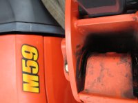
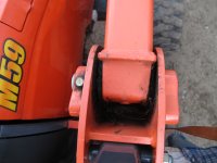
But the unknown factor is what will cause the pin or any pin to fatigue and shear eventually and that is... How much clearance there is between the outer bosses on the loader frame and the pivoting point on the loader that the pin fits through. That is the 64 dollar question, shall; we say....

If the pivoting part of the loader that the pin fits through is small in length to the point of being excessive, failure will occur and thats what none of us actually know. I do know on my big Kubota's the boss to pivot fabrication spacing is minimal, about 3/32" on each side. Excessive spacing will cause failure every time.

BTW, a Grade 5 will yield (plasticize) more in respect to elongation that a Grade 8. I happen to be in the alloy steel business, thought in flat rolled high strength not fastneres but a quick look at the ASTM specification will bear that out.
 
   / More M59 repair fun. #42  
BTW, a Grade 5 will yield (plasticize) more in respect to elongation that a Grade 8. I happen to be in the alloy steel business, thought in flat rolled high strength not fastneres but a quick look at the ASTM specification will bear that out.
Yes. That would be expected. The Gr8 supports larger elastic deformation tho before it goes plastic/suffers damage. Particularly with forward and reverse loadings you dont want to go too near the yield point. Altho the metal will strengthen at early yield, that robust response is only a benefit if loading is only one direction . ... The response does not tolerate reversal well.
 
   / More M59 repair fun. #43  
Which begs to ask just how much clearance there is between the loader frame ears and the moveable portion of the upper arm and or the weldment. Without pulling my loader again (no small feat on my large frame Kubota, I see to remember that the upper arm (a fabricated weldment) has a heavy walled tube welded into it. If the tube is too short (which creates excess space between the uprights and itself, that imparts what I would assume a failure load on the pin.

Something to ponder and keep in mind if I remember correctly this isn't the first time so I wonder if, when he pounded to uprights back, he didn't aggrivate the condition by increasing that gap. Wouldn't take much. There is a lot of strain in that area. I know my big loader is heavily gusseted in the upright area.
 
   / More M59 repair fun.
  • Thread Starter
#44  
i had a peice of 3" sqruare channel that I cut to the same measurement as the other side and used it as a spacer. 2 5/8" if I remember. As far as lateral movement, the is a lot of side movement on the loader. Like a 1/2". Let the pressure off and you can move cylinders back and forth.
 
   / More M59 repair fun. #46  
Oh, & Hearsheyfarm, I really like your attitude! You realize that you have a few years & hours on the machine, also don't abuse the machine, but get "every nickel" out of it you can, (like we all do). You wish that some things were a little "beefier" from the factory, but when you have troubles, you just take care of it without coming here crying. :thumbsup:
This sounds like another accoutant vs. design engineer conflict that is just a fact of life good or bad.
 
   / More M59 repair fun. #47  
'


Whoa! ... Perhaps we need a little background on material. - All material, steel included, acts like a spring until it doesnt. That is to say it flexes when it is loaded. The more load the more flex. But until the flex exceeds the elastic limit of the material the piece will return to its original shape after the load is released. If instead load continues to increase you finally reach a point that the metal "gives" [yields plasticly] and begins to bend. You never want to reach this point in a loader pin because they see repeated load reversals in their use and will bend back and forth.

A stronger pin is a better spring. A pin of the same size has almost exactly the same stiffness as the weaker steel; flexing the same per given load. It is stronger because at the point the weak pin is damaged [bends] the strong pin is still just flexing. ... So you want the pin made of the stronger steel if ample sized pins arent used. The stronger metal is undamaged by the load and will last. ... Talking equal size; a Gr5 will last where a grade 3 wont, and a Gr8 will last where the Gr5 wont. But, since theres no difference in the stiffness theyll all act the same in the assembly seeing the Gr3 load.

All pins bow in response to load. Thats the problem with using a small pinned assembly and upgrading to a strong alloy pin to make it survive. The strong alloy "makes" its strength by being able to withstand higher deflection without bending. The strong alloy bows back and forth - itself happily enuf, but slowly wallowing out the ends of the crosstube bore because of the intense forces out near the shear point. The strong solid pin happily accommodates the bellmouth by bowing a little further. The ones that are grooved at the center start to die. That bowing is concentrated there by the full cross section on each side, finally exceeding the elastic limit of the surface metal in the groove. It cracks at the groove - a cross hole accentuates the start of cracking. With equal loading the Gr8 would have gone a little longer due to its higher elastic limit but as the bellmouth worsened ... you get the idea.

Since stiffness goes as the cube of thickness [in this case diameter roughly], big pins are the answer - absolutely if drilled and grooved. There is no point paying for high strength steel because bowing is so miniscule as to pose no fatigue threat. The pivot remains happy thru a long life.
,,, If a maker goes the small strong pin route to support high load theyd better use solid pins. Still the relatively great bowing under high load will wear/deform the joint much faster.

What an excellent explanation, Spyderlk! The physics is sound, not only does your theory fit all the facts that we know about from Hersheyfarm's descrition of the failure, it even puts the forces and their effects into the right locations. I couldn't just leave such a good explanation to be read once, but had to quote it again.

That's an especially nifty idea about the concentrated forces "wallowing out the ends of the crosstube bore. I suppose the same applies to the loader frame ears? Anyway, it was a nice touch taking the idea of that wallowing and allowed it to cause increased bowing of the pin until yield leads to fatigue....a failure that would be concentrated exactly at the cross section where we know that Hersheyfarm's original break happened.

For me, it was when you includ the wallowing that helped me to picture the failure. Before you introduced that idea, I just couldn't square the physics and the failure.

Yes, we have to remember that in the beginning, Everything Flexes.....Nicely done.
In fact, this whole discussion about "how materials work" reminds me of the best of those engineering textbooks. Exciting stuff - both then and now.
Thanks again. From now on I'll be looking at loader pivot construction in a whole new light.
Enjoy,
rScotty
 
   / More M59 repair fun. #48  
i had a peice of 3" sqruare channel that I cut to the same measurement as the other side and used it as a spacer. 2 5/8" if I remember. As far as lateral movement, the is a lot of side movement on the loader. Like a 1/2". Let the pressure off and you can move cylinders back and forth.
,,,,,,,:eek: ,,,Now it comes clear. That is a huge gap for the pin to cross unsupported. Kub has made a mistake - more encompassing than I thot. Have you spoken to a service rep? Corporate is not going to notice a trickle of issues unless you reach higher up the chain and explain it to them. While solely using a solid pin would work, the assembly is self abusive. - The boss across the end of cyl needs to be widened.
 
   / More M59 repair fun. #49  
,,,,,,,:eek: ,,,Now it comes clear. That is a huge gap for the pin to cross unsupported. Kub has made a mistake - more encompassing than I thot. Have you spoken to a service rep? Corporate is not going to notice a trickle of issues unless you reach higher up the chain and explain it to them. The boss across the end of cyl needs to be widened.

Not sure it's a mistake pr if the guy cutting the blanks on the horizontal bandsaw didn't cut some too short (misreading the print) and they went into production units and weren't caught before being fitted. I surmised from the outset that the welded in tube was too short.

Reason I say some is it's not a widespread issue, in fact, so far it's just this one loader. People make mistakes all the time, thats human, but it should have been checked and rejected and it wasn't (by QC).

Finally, did Kubota build the loader at all or did Woods? I was under the impression that Woods built or has built some Kubby loaders.

Things to ponder, also things to address with Kubota in Torrance, California.
 
   / More M59 repair fun. #50  
Not sure it's a mistake pr if the guy cutting the blanks on the horizontal bandsaw didn't cut some too short (misreading the print) and they went into production units and weren't caught before being fitted. I surmised from the outset that the welded in tube was too short.

Reason I say some is it's not a widespread issue, in fact, so far it's just this one loader. People make mistakes all the time, thats human, but it should have been checked and rejected and it wasn't (by QC).

Finally, did Kubota build the loader at all or did Woods? I was under the impression that Woods built or has built some Kubby loaders.

Things to ponder, also things to address with Kubota in Torrance, California.

What an interesting thread. I went out and took a look at my M59 this morning. I expected to see something like your speculations....something familiar to a US design mind. Something hopefully better made than an add-on Wood's loader because those are add-on's for farm tractors and this loader was deliberately designed as Kubota's entry into the the construction machine market. So they would be expected to assume that the loader would see somewhat higher stresses and lots more repetitions.

Looking at our M59, I can see that these upper loader arm pivots are NOT "welded on tubes"...nor is the piece a "blank cut on a horizontal bandaw". Arm pivots made like that would be appropriate for a lower stressed farm loader. But here we have a cast and machine-bored end piece that is welded (nicely) onto the end of the arm. It even has a boss especially cast as a place to drill and tap for a zerk. The problem - other than the unused zerk boss being in the wrong place - is that the cast piece is only 2.75" wide whereas the loader frame mounting space is 3.75" wide there. Why? The cast piece could easily have been wider....there's sure room for it. As it is, the cast pivot piece they've welded on is narrower than the arms themselves. All in all, that cast piece looks suspicioulsly like it was borrowed from a smaller loader - right down to the unused zerk boss.

Here's a couple of photos:
 

Attachments

  • showing unused zerk boss.JPG
    showing unused zerk boss.JPG
    1.9 MB · Views: 138
  • top view.JPG
    top view.JPG
    2 MB · Views: 149
 
Top