Apologize for long message, but those considering repair for slowing/stalling will likely find this useful.
My JD mower w/ TuffTorq T40A has 330 hours. For awhile now it’s been slowing down very noticeably before a FLAT half acre is complete. Reverse goes to a crawl in that time barely moving. Attempting an acre it slows to halt. Let sit and cool, and then can finish. May take couple cool down sessions to get job done. So it’s just about total toast. From this thread I learned the likely culprits causing the failure were the tranxaxle center case and the pump and motor “revolver’s” (with spring loaded pistons) that ride on the center case faces. I opened the transaxle and inspected everything. Here’s a record of what I did and a few new tips.
The motor & pump “revolvers” and their pistons are very hard steel. I mic’ed piston diameters and their bores. All pistons and mating bores are within .001”. So, those clearly do not wear even on a unit like mine that is almost total toast. What wears is this: The center case is soft aluminum and it’s machined faces that contact the “revolver” faces score easily and deeply. If overheated, the microscopic carbon particles (i.e, hard carbide) formed from burned oil probably grind & cut the aluminum easily. But the revolver pistons & bores tolerate it fine. While the pistons & bores show negligible wear, the bottom faces of those revolvers were also scored/galled from probably combination of carbon and contact with the galled faces of the center case. The revolver faces aren’t galled nearly as deeply as the center case(which would be expected of steel vs. aluminum) but they are clearly scored.
If you replace or grind/polish only the centercase faces, and not the revolver faces, when you put it back together the scored revolver faces will quickly re-rake the centercase faces and you’ll be toast again shortly. So, to get maximum lifetime, you need to replace or grind both faces of centercase AND both revolver faces that sit on those centercase faces. As I said, I found the center case faces had much more severe and deeper scoring than the revolver bottoms. On the center case, the large diameter motor face (the face where the bypass pin falls out) was scored much worse/deeper than the pump face.
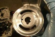
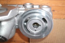
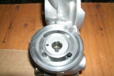
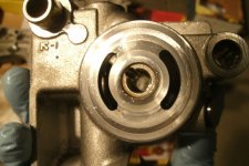
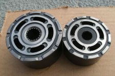
Since the three parts end up about $300 from Tuff Torque, I decided to try grinding/polishing the center case faces and the pump & motor faces (the faces of the “revolvers” which contact the machined faces on the center case). Here’s what I found.
I called machine shops and found hourly rates $70-100/hr. The center case is a complex shape and the shop I visited had no machine with a working head that could get to its faces…the head would collide with other features on the case before getting down to contacting the face needing machining. Even if one had such a machine, the center case needs to be held securely and level (so needs some sort of fixture to hold & present to machine head), and the machine would have to be prepped & setup for the job. At $70+/hour, seemed just the setup time could easily exceed the $25 others have reported for grinding. I couldn’t find a shop that’d come anywhere near that. Buying a new center case for $125 plus shipping seems certainly cheaper than machining at a shop (if you can find a shop with machine that can do it). A shop could grind/mill the revolvers because they are a simple cylindrical shape. But no takers for $25 on the center case…just laughs. So I decided to hand grind similar to SJSmith.
Attached is picture of my setup.
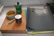
I used gray abrasive (sand) paper (carbide?) used for metal work vs. ordinary sandpaper. For doing the center case faces, I got a 2” diameter, 2” high cylindrical chunk of dense, HEAVY stainless steel to use as a “puck” for mounting the carbide paper (instead of oak block sd SJSmith used). I had both ends milled flat (that was way cheap). I used 2-sided tape to affix carbide paper to the puck. I pulled guard sheet of one side of thin 2 sided tape, and affixed tape to the flat end of puck (tape only 1” wide, so took 2 pieces to cover entire end of the puck). Then I turn puck over onto the tape and exacto knife around the perimeter of the puck to cut off excess tape. Then I remove tape guard sheet from the exposed side of the tape and press the puck onto backside of carbide paper. I use exacto knife to cut paper around perimeter of puck. I end up with an extremely flat hard grinding surface on an easy to handle but heavy cylindrical puck. I turn the puck over and tape another piece of carbide paper onto its other end, so I can use both ends. I started w/ 320 grit as did SJSmith, and that seemed good for starting. On the other end of puck I put 400 grit. As the paper loads up with sluff from grinding it gets less effective, so I pull off the worn paper & tape and replace it as needed. I put 5-6 small drops of aluminum cutting oil on the 320 grit and grind in figure-8 pattern, rotating the centercase around periodically so I remove material evenly around the whole surface and don’t get a low spot from favoring a particular area. I added more oil if puck felt sticking/skipping or felt too dry. I did not push down on the puck because my pushing would not stay even and maybe I’m **** but I didn’t want to risk flatness problems or uneven grinding. I just pushed the puck around laterally and let its heavy weight do the grinding job because that weight stays consistent. I ground w/ 320 grit until all wear marks disappeared. The motor face was clearly scored deepest and that took well over half hour because some tracks were pretty deep. Took awhile. Not easy 15 minute job for me. Maybe deeper scoring in mine compared to SJSmith’s. I probably could’ve cut the time down had I applied vertical pressure on the puck. The pump face on the case went much faster…it wasn’t scored as deeply and its smaller diameter helps cut the time needed. After no sign of gall marks w/ 320 grit, then the polishing starts: I went to 400 for just a few minutes…until the puck slides evenly and smoothly. Then on to 600 (again just a few minutes until it glides smoothly). I did a final pass w/ 12 micron paper (that paper was yellow, not gray). These surfaces are probably now better than new. How long it takes in total is also affected by how smooth you want it to be, but fair to say once you dive this deep into it, you don’t wanna half-*** it.
For the revolver faces I didn’t use the puck. I had a surplus piece of flat granite tile laying around and placed carbide paper on that (grit side up of course), then put revolvers on that and pushed them around (w/ machining oil) just like I pushed the puck around. Not a quick job there either. The face of larger diameter motor took more time because it was scored more than the pump face (just as its opposing center case face was far more scored than the case’s pump face). Also, both revolvers are hard steel so even though scoring isn’t nearly as deep as on the case, it takes awhile to work them out of the steel. Again, if I pressed hard on the revolvers while grinding, it may have reduced the time.
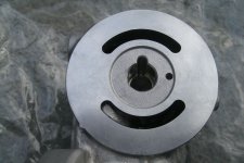
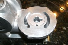
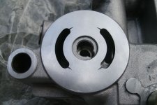
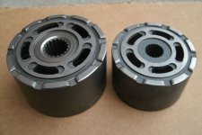
Some forum posters caution about assuring that after grinding the motor face of the center case, washer #39, which sits in a recess on the case, doesn’t stick out above the polished surface of the center case face (it shouldn’t “stand proud”). My case’s motor face needed so much material removed that after grinding, a straight edge spanning across that face pressed on the washer enough to hold it in place slightly. It stood proud. However, notice that not only is the case recessed for that washer, but the motor revolver’s face is recessed for the washer too. The sum of those recesses gives ample free space for free movement of the washer. I put the washer in the revolver recess, then placed revolver on the center case face, and when I shake the two together, I can hear the washer rattling inside. You could grind the center case down darn far before that washer would stand proud enough to interfere with motor function. In operation, no doubt oil injected under pressure by the pump fills the cavity around the washer and prevents rattling.
All this grinding produces a lot of grit. ANY residual grit left on the parts will trash ALL the hydrostatic parts in short order and waste all your effort. Thorough cleaning is really important. The revolver grit may eventually be captured by magnet, but until it is, it’s disaster…and the aluminum grit is non-magnetic. It’ll just keep circulating. Aluminum grit from 400, 600, or 12 micron carbide paper may be too fine for the ring filter to trap? So, the parts need to be cleaned THOROUGHLY. I used a mineral spirits bath with stirring & dipping, then bathed parts in detergent degreaser like Super Clean heated to “coffee hot” to let convection flows work on the grease & grit (like when cleaning a carburetor). Finally I blew everything out. I then sprayed w/ brake cleaner and blew again.
I inspected the differential side and it’s gears. That magnet was totally covered by debris. There was small amount of steel shards & shavings in bottom of transaxle case, but alarmingly big in size, and under brake pads, and more ready to come off many of the gears. No major damage to gears or missing/broken off teeth, but certainly evidence of plenty of wear. But looked intact so I just cleaned what I could by wiping & w/ magnet wand. Replaced nothing on differential side.
Before reassembly, I bathed the center case faces and revolvers and their pistons & springs in 5W50 oil. The '50' number means greater tolerance to high temps w/o burning (the bigger number the better). It's burning oil that produces the hard carbon particles that wear things out. If you go w/ 20 or 30W, your oil will burn at lower temps.
On reassembly, the challenging thing to install is the big assembly you seat as a unit: the center case, motor revolver, swash (prism shaped plate & bearings), with the drive shaft going through all that and having the bearing, brake rotor, & drive gear on the left side (see plenty of other pictures in this thread that show this set of parts). As you install, you have to hold those parts together and keep one finger over the access hole for the bypass pin on the right side, to keep that pin from sliding out. The motor piston springs have to be compressed making the whole assembly spring loaded as it’s installed. It fights against you. There are 4 interferences that have to managed to snap the assembly back in. 1) the brake rotor has to go between the brake shoes. To eliminate this challenge, I removed the left brake shoe and just reinstalled it after completing rest of the installation. 2) the bearing just to the right of the brake rotor has to fit into a cradle in the transaxle housing. 3) the vertical bypass lever rod (underneath so you can’t see it) has to snap up and into the centercase access hole where the bypass pin is contacted. 4) The two small forward/reverse pistons on the center case upper right have to compress to slide by the forward/reverse linkage part in the transaxle case. The biggest problem for me was that after I got everything else nearly in place, I couldn’t get the bearing on the far left side to align with its cradle, so I couldn’t fully seat the whole unit. I didn’t want to urge it into place w/ a mallet. After many attempts I found the easiest way to do this install. Start by removing leftmost brake shoe. Hold the whole assembly w/hands on each end and a finger on right hand reaching down & holding in bypass pin. Tilt the assembly so right side is higher than left (this also helps keep the bypass pin in place). Start inserting the left side first, getting the bearing and rotor roughly in place, paying special attention so the bearing will align w/ its cradle…this may require sliding the driveshaft out or in. Once those are certain to go into place, deal with the swash plate (the prism shaped piece & it's bearings which contact the revolver pistons). Then, you may need to squeeze the right hand toward the left (the motor piston springs may need to be compressed) to get the bypass linkage rod to align w/ the hole accessing the bypass pin. Finally, with left now almost in place, as you lower the right side the small forward/reverse pistons on upper right may need to be pushed in so that these pistons slide past the linkage part in the transaxle case. I had to use a finger to push the top small piston in to get it to clear the interfering linkage, but then everything seated fully with just a little pushing down. Doing it this way (start on the left and work right) made it easy & quick, and despite the whole thing being spring loaded, it could be installed and fully seated into place (without anything popping back up) without using any rubber mallet to convince things.
Overall, next time would be a whole lot faster, having assembled everything needed, and not stopping and checking things and wondering about things so often. Once you’ve elected to get inside the transaxle, it’d definitely be worth grind-polishing these parts as opposed to $300 for replacements from TT…IMO.


