1700 Engine Rebuild

   / 1700 Engine Rebuild #1  

jones6780

Gold Member
Joined
Nov 30, 2008
Messages
418
Location
Lizella, Ga.
Tractor
Ford 1700 4wheel drive, Yazoo/Kees Max2 Zero Turn
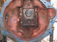
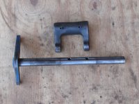
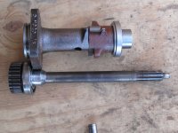
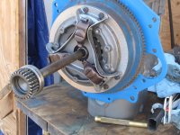
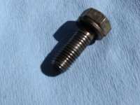
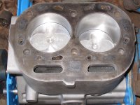
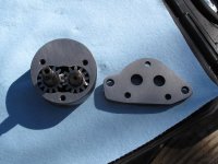
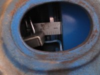
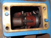
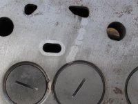
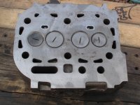
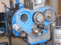
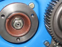
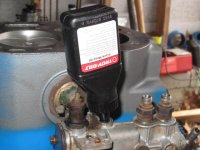
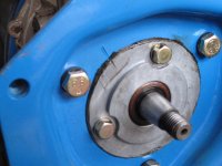
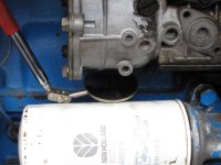
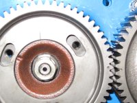
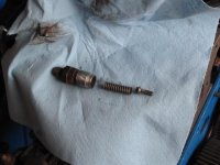
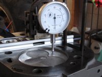
Well the day today was absoutletly great. It started off in the low 30's and finished up in the low 70's and not a cloud in the sky. I finally had time to get back to working on the tractor engine. I have priced a clutch alignment tool at $31.00. Now some folks call me tight but, I just can't spend that much on a one time use item. At least I hope I don't need it agan. I wanted to look at the front seal on the transmission and in the process pulled the front shaft out to use as an alignment tool. In the first picture you can see the result. The second picture shows the arm and forks that operate the clutch. The fork was attached to the arm with 2 roll pins and the pins were safety wired in place. The next picture shows the housing (cleaned with new release bearing) and transmission input shaft. The housing was held on by 4 bolts and has an "O" ring and shaft seal. The seal looked good with no signs of leaking but the shaft had a bit of corrosion as it has been sitting up for several years. The last shot is the shaft in use to align the clutch. Oh by the way the end of the crankshaft is tapered and the flywheel mounts with a key and a 2 1/2" nut torqued to 325 ft lbs.
More to come. Let me know if there are particular photos you want to see.

Russell
 

Attachments

  • tractor 007.jpg
    tractor 007.jpg
    599.5 KB · Views: 1,046
  • tractor 005.jpg
    tractor 005.jpg
    688.9 KB · Views: 445
  • tractor 008.jpg
    tractor 008.jpg
    656.7 KB · Views: 505
  • tractor 003.jpg
    tractor 003.jpg
    603.6 KB · Views: 1,227
   / 1700 Engine Rebuild #2  
Russell,

Great pics, the kind I can really dig.:D:D You'll have this thing puring like a kitten before too long. If possible I'd love to see the picture where you can show pressure plate thickness and brand new clutch disk. Picture of Rocker arm assembly, push rods, cam shaft and stuff like that will be great. This should be quite helpful for many and 1700 owners in particular.


JC,

PS.How about a picture of the rear main seal. did you put a new one there?
 
   / 1700 Engine Rebuild #3  
Nice pics jones! Please keep them coming. I was looking at the throw bearing picture, mine is making noise. Hopefully I wont have to address that too soon.
 
   / 1700 Engine Rebuild #4  
Looks super clean, did you sand blast the motor, In that fourth pic it looks like it.

I don't know that much about the innards of this machine but am learning.


EDIT: sorry I had you mixed up with Piper pacer who was just doing tranny/clutch work, you already stated you had the block vatted. how about some pictures of the head repair.

Thanks, JB.
 
   / 1700 Engine Rebuild
  • Thread Starter
#5  
Sorry JC, the engine is mounted. Here is a shot through the inspection port with a scale for ref. The engine is getting all new seals so yes the rear is new. The oil pump in the second shot was barely in tolerance on endplay and fine for side clearance. I took the housing and sandpaper to the drill press table and polished off a little. It is a tight .003 now. I guess everyone recognizes new pistons. Be careful installing rings. There are 3 compression rings and all 3 are different. Just follow the book. The bolt is one of 12 that attach the front frame to the block. Notice the wear under the head. The bolts were slightly loose and wore down the threads as the frame moved. I will replace these but I will try to find some that are not threaded all the way to the head. The frame is about 1/2 in thick so the best bolt would have 1/2 unthreaded shank. The last shot is with the steering column removed. You can't do anything but look in the hole or maybe lube the slide for the throwout bearing. More to come.

Russell
 

Attachments

  • IMG_0166.JPG
    IMG_0166.JPG
    79.7 KB · Views: 356
  • IMG_0167.JPG
    IMG_0167.JPG
    166.8 KB · Views: 587
  • IMG_0148.JPG
    IMG_0148.JPG
    148.7 KB · Views: 357
  • IMG_0161.JPG
    IMG_0161.JPG
    97 KB · Views: 546
  • IMG_0162.JPG
    IMG_0162.JPG
    126.4 KB · Views: 493
   / 1700 Engine Rebuild #6  
The last shot is with the steering column removed. You can't do anything but look in the hole or maybe lube the slide for the throwout bearing. More to come.

Russell

Very interesting picture. It took more than 5 minutes to figure it out looking at my own pics as I initially could not identity the access opening till I looked at the bolt spacing on the steering column. I could not guess that in a million years:D it is hard to find detail as such looking at the manual. My clutch is a good shape and I have about 5/16" of disk material left, seems not much less than a brand new one. Was the rear seal part of the transmission input shaft housing?? was the hole in the bottom of the housing a tell tale hole if you had a seal leak in pic3 from the left in post #1?

Thanks for the great pics.
JC,
 
   / 1700 Engine Rebuild
  • Thread Starter
#7  
Was the rear seal part of the transmission input shaft housing?? was the hole in the bottom of the housing a tell tale hole if you had a seal leak in pic3 from the left in post #1?

The seal is actually the Fwd transmission seal and it is in the flanged end of the housing. The holes you see are on the side of the housing the spring is on top. If the seal leaked, it would run all the way to the end of the housing....Hmmm maybe I should have drilled a hole to let it leak out farther from the clutch??
Anyway I QUIT.....for today. Have you ever looked and not found? I have 3 bolts to mount the injector pump that I can't seem to find. I guess I am looking too hard. Here are more photos. The first is timing gears minus the injector, no bolts remember. Next is the injector and drive gear. I sctatched wittness marks before removal but I will follow the book for timing. the next are a couple of the reworked head all the valves have new seats installed. I haven't started with rockers yet.

Russell
 

Attachments

  • tractor 012.jpg
    tractor 012.jpg
    109.6 KB · Views: 474
  • tractor 011.jpg
    tractor 011.jpg
    150.7 KB · Views: 516
  • tractor 010.jpg
    tractor 010.jpg
    160.2 KB · Views: 1,109
  • tractor 009.jpg
    tractor 009.jpg
    164.7 KB · Views: 1,733
  • tractor 013.jpg
    tractor 013.jpg
    199.5 KB · Views: 483
   / 1700 Engine Rebuild #8  
Hey Jones,


That bolt you showed is that a head bolt??? When I had the head shaved on my 9N the machinist gave me a set of washers to put on the head bolts, he had me do the regular torque twice. They never came loose. The washer had a special shape that acted like a lock washer. A machine shop should know what they are.
 
   / 1700 Engine Rebuild #9  
Have you ever looked and not found? I have 3 bolts to mount the injector pump that I can't seem to find. I guess I am looking too hard. Here are more photos. The first is timing gears minus the injector, no bolts remember. Next is the injector and drive gear. I sctatched wittness marks before removal but I will follow the book for timing. the next are a couple of the reworked head all the valves have new seats installed. I haven't started with rockers yet.

Russell


Yep ...I sure have. It all starts out organized for me till I hit a snag, and then
I'll then start getting ahead of myself and lose it all together:eek:
A lot of time I use cereal box card board and hand sketch the out line with a sharpie, Poke a holes for the bolts and insert the bolts. No all the bolts are same lengths and hate to put a short bolt in a long hole and vise versa. I use my dremmel tool to put whiteness mark on on parts as well. I have not taken my injector off and it seems that is well timed so I put a mark on mating parts for future reference. I looked at the timing method recommended and it seems pretty easy. I'm impressed by your meticulousness. Things happen, but much of your problems would be non-existent if the previous owner gave a touch of basic (heat removal and proper internal lubrication) TLC .

JC,

Keep the pics coming:)
 
   / 1700 Engine Rebuild
  • Thread Starter
#10  
My 2 cents worth on injector pumps. Note the first picture of my other 2WD tractor. There are no drain or fill level plugs. I looked on the back side and none there either.
Anyway I got the bolts and mounted the injector pump on my rebuild engine. The second shot shows the wittness mark to align the pump itself. Third is the 3.4 oz of oil to fill the injector. 4 is the flange mount for the gear and 5 is the gear installed. Note the timing mark on the 2 gears and also the wittness mark straight up on the pump gear. With marks aligned and bolted I removed the front fitting spring and plunger from the top of the pump shown in picture 6. I just followed the instructions in the book to use a dial indicator picture 7 and checked the timing one more time. Everything was just right.
 

Attachments

  • tractor 020.jpg
    tractor 020.jpg
    64.1 KB · Views: 435
  • tractor 019.jpg
    tractor 019.jpg
    58.3 KB · Views: 441
  • tractor 018.jpg
    tractor 018.jpg
    48.8 KB · Views: 505
  • tractor 014.jpg
    tractor 014.jpg
    54 KB · Views: 434
  • tractor 021.jpg
    tractor 021.jpg
    65.1 KB · Views: 838
  • tractor 023.jpg
    tractor 023.jpg
    62 KB · Views: 379
  • tractor 024.jpg
    tractor 024.jpg
    55.2 KB · Views: 506
 
Top