KYKub
Silver Member
The temp gauge on my G1900 has not worked since I bought it second hand. Never moves off the bottom peg. Cleaned all the grounds I can find, replaced all 3 fuses, and replaced the temp sender. No improvement. Fuel gauge, status lights, and hour meter work fine.
If I ground the temp sender wire a warning horn sounds (loudly!). Just about came out of my skin when the horn sounded since I didn't even know it had a horn! Needle didn't budge,although something must be working if the horn sounds.
Wondered about combination box, but from what I can gather it has nothing to do with temp gauge. Is that right?
Thinking I must have a bad gauge, I replaced the instrument cluster. Still nothing!
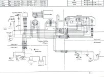
So, I now believe there is a problem in the wiring between the temp sender and the harness that connects to the instrument cluster wiring. I don't really know how to read an electrical schematic so I would appreciate any help. My specific questions:
1) Does the "Y" wire run from the temp sender directly to the second position, right side of the instrument cluster wiring harness? (see schematic) The one directly under the top position with an "X" (unused, I believe). it looks that way in the schematic, but then where and how does it connect to the horn?
2) Does anyone know what "I", "E", and "U" labels on wiring stations on the back of the temp gauge stand for?
3) In testing wires for continuity, would I check between the temp sender end and the harness end connection of the "Y" wire?
4) Do I need to test the "I", "E", and "U" wires? If so, can anyone help me understand where they go? I don't understand the schematic.

Thank you for helping me wade through this quagmire!
If I ground the temp sender wire a warning horn sounds (loudly!). Just about came out of my skin when the horn sounded since I didn't even know it had a horn! Needle didn't budge,although something must be working if the horn sounds.
Wondered about combination box, but from what I can gather it has nothing to do with temp gauge. Is that right?
Thinking I must have a bad gauge, I replaced the instrument cluster. Still nothing!
So, I now believe there is a problem in the wiring between the temp sender and the harness that connects to the instrument cluster wiring. I don't really know how to read an electrical schematic so I would appreciate any help. My specific questions:
1) Does the "Y" wire run from the temp sender directly to the second position, right side of the instrument cluster wiring harness? (see schematic) The one directly under the top position with an "X" (unused, I believe). it looks that way in the schematic, but then where and how does it connect to the horn?
2) Does anyone know what "I", "E", and "U" labels on wiring stations on the back of the temp gauge stand for?
3) In testing wires for continuity, would I check between the temp sender end and the harness end connection of the "Y" wire?
4) Do I need to test the "I", "E", and "U" wires? If so, can anyone help me understand where they go? I don't understand the schematic.

Thank you for helping me wade through this quagmire!
