Help!!!

   / Help!!! #11  
That parts diagram looks remarkably like an old Flathead V8 Ford clutch assembly. Some differences, the clutch lever shaft, #26, is above the input shaft instead of below it. I'm going to make a rash assumption your transmission/clutch is similar to an old Ford.

There is a key part missing from your diagram, the bearing retainer. This is probably part of the transmission parts diagram. The transmission input shaft bearing retainer is more that just a bearing holder. It also has a snout on it which extends out from the transmission and covers the input shaft for a bit (1 to 2 inches). The throw out bearing, #24, and throwout holder, #23, slide on this part of the retainer.

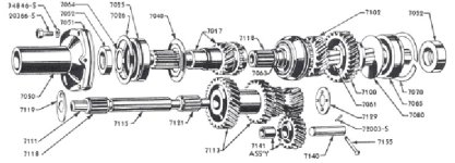
I've attached a diagram of a Ford transmission, the bearing cover is #7050. Notice the eylet on the flange (facing out).

If your transmission is anything like this, your bearing retainer is probably broken. I had a car once with the snout completely broken off, the throwout bearing was running on the input shaft--it almost worked.

Dry assemble the clutch on the input shaft. Is there a surface for #23 and #24 to run on? Is part #23 loose and running on the input shaft? If so the snout is broken off the retainer. And, since you can't find any eylets for the springs, they may be broken too.

Hopes this helps.
 

Attachments

  • 466044-transmission.jpg
    466044-transmission.jpg
    57.2 KB · Views: 219
   / Help!!! #12  
Ozarker, Could it be that parts #2 & 3 are some sort of retaining pin for springs? It's kind of hard to tell by diagram if the springs would be long enough to reach the pins, Also I don't see any other springs on diagram that would keep through-out bearing off the diaphram...
Assembly #22 thro-out and guide(retainer) are they held together and by what means,Does the thro-out have ears or eyelets?Could it be that the springs are for holding assembly#22 together on the fork? And if so ,is there is another spring (not pictured)for holding bearing off the diaphram ?
 
   / Help!!! #13  
In the drawing it looks like there is a hole in the main housing straight back from the bushing hole for part #4. It looks like it would be about the right distance for the spring length. Providing there is a hole on the other side in the same spot.
 
   / Help!!! #14  
Ozarker,

I am trying to figure out if a repair we made recently is not unlike your problem. This customers model had serious clutch problems and we discovered two springs lying inside the housing.

We pulled the steering box/shaft to locate where the cast spring anchors were. Gone, nothing (small broken cast pieces about the size of a fingernail).

We actuated the t/o bearing travel, determined the distance necessary, and drilled two 1/4 inch holes on the outside of the case. Installed 1/4 20 bolts, anchored springs and operated clutch pedal.

It worked excellent, and by appearances looked factory.

I hope it's something similar as this was an E Z fix.

Mark
 
   / Help!!!
  • Thread Starter
#15  
Yes, that hole has a bolt in it holding the bracket that the dash and tank is bolted to. If I couldn't find out how the original was set up, my plan was to use that as an attaching point. It is in approximately the correct position for the spring but a little high.

I think Mark777 has solved the mystery for me and provided the solution both here and in a reply he made to me in another forum.
 
   / Help!!!
  • Thread Starter
#16  
Thanks for the reply both here and in the other forum Mark. I asked a question over there that I probably already know the answer to but I want to make sure. No need to answer in both forums.

Was the original cast tab located on the sides of the housing so that the springs pulled horizontal to the shaft or were they up high closer to the steering gear?

Of course I guess when I go clean all the old built up iol and dirt out of the housing tomorrow I will see where they were.

Thanks again. Your solution sounds like the perfect way to solve this problem.
 
   / Help!!! #17  
Ozarrker,

We installed bolts horizontal with the shaft and t/o bearing travel. Sorry I dont have any pix, but it was a few inches below the machine surfaced hole where steering box mounts.

As the cast was very dence I used a 1/8th pilot bit first and followed with 1/4".

On this model it would seem one broke long before the last one let go, as there were stress ware marks on shaft from uneven pressure during travel.

Can't think of any reason why it won't work on your model.

Mark
 
   / Help!!! #18  
Cant find a decent picture, maybe too late, as I hope your problem is solved by now. If not here is one for reference.

This 1610 has the same pins as described in your parts blowup.

Mark
 
   / Help!!! #19  
might help even more if I included the picture.
 

Attachments

  • 467550-1601 163.jpg
    467550-1601 163.jpg
    61.1 KB · Views: 153
   / Help!!!
  • Thread Starter
#20  
Thanks again Mark. I printed out your solution and took it to my mechanic Friday. We discussed a few options then I turned the project over to him and went to work. Hopefully he will have it back together this week and he will go easy on me for all the extra labor.

It is times like this when I wish I had my shop built so I wouldn't have to pay someone else to do things that I could easily do myself. But I just didn't want to break the tractor in half on my gravel parking area behind the house.
 
 
Top