I am not sure of the options Massey offered on this model, maybe that is why the diagram is not complete, because of other options for it. I bought the tractor used in 2013 with 800 hours on it. I now have 1254 hours on it and have not had any problems with it until now. It is a factory stock tractor because I can find all the parts in my Massey parts book. I called it a priority valve because on the valve it self there is a tag on it that says priority valve. In the last picture I sent, you can't see the word priority because of the line and in the parts book it is listed as priority valve. The diagram I drew on, I was standing at the tractor and followed the lines and filled in where they went. The priority valve has one input line and one output line and the hole I been talking about. I don't know why the solenoid valve has two return lines. All my pressures are good. The only test left, that I haven't done is the flow test. The priority valve is $700 and solenoid valve is $1000 and only available through Massey and before I spent money guessing I was just trying to get some information. I did see a flow meter I could purchase for around $500.Well, at least you do have a hydraulic diagram. That system is just enough different from a standard one to make a diagram a real help. Your hand drawn in PTO part make perfect sense, but the fact that they were not there originally makes me wonder if the (Independent)PTO was an option or afterthought. Do you know?
As you have drawn it, what you are calling the "priority valve" - not shown originally - has an input from the IPTO pump and an output to the solenoid flow switch. But I am puzzled why you are calling it a priority valve? A priority valve divides an input flow into two outputs. So if that is a priority valve, it should have an input and at least two outputs. Where is the other output?
Is the other output the missing plug?? And if so, is the missing plug in fact a relief valve? Or the outlet from one? If so is there a relief valve inside that aluminum valve block? In that case, the priority would be IPTO vs RELIEF and that would make sense. One would expect a relief valve somewhere in the IPTO system in case the PTO is stalled. Otherwise a stalled PTO would blow up the pump and maybe break the shaft.
Then we go over to the soleoid flow control (on/off) and I see that you have drawn in two return lines. Why are there two? Any idea?
Flow meters are very expensive but wonderful tools to have. I don't know of a small one for measuring flow in home shops for compact tractors. Even large dealers there days are unlikely to have a flow meter, although diagnosing hydraulics without one is a lot like doing electricals without a VOM.
Don't let me talk you out of a flow meter, but also consider buying or making a hydraulic pressure test kit (Amazon has them), and using that meter to plug the hole in the "priority valve". If so you might want to incorporate a relief valve in that test line just in case. It might show no pressure unless the IPTO is turned on and then stalled, and I would not recommend stalling the IPTO as a test even if you could....because it might cause major damage... Probably would.
rScotty
You are using an out of date browser. It may not display this or other websites correctly.
You should upgrade or use an alternative browser.
You should upgrade or use an alternative browser.

/ Independent PTO problems
#11
oldnslo
Super Member
Dtj
Per the schematic you posted this tractor has two separate pumps, P1 for PTO and the another for ferguson lift. Is Ferguson lift the 3 point? Also shows P2 for aux hydraulics. If that is correct the PTO should have no influence on the 3 point since only common point appears to be suction or pump inlets.
Is it possible the PTO is fed by the same pump that feeds the 3 point? Some systems have a pressure reducing valve or an orifice supplying PTO from main circuit.
Dman1981
Gold Member
- Joined
- Jul 28, 2023
- Messages
- 324
- Tractor
- Kubota bx2200
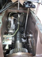
Yes, No. 10 on the schematic is the one that is for the 3 point lift in this picture, the one with the stand pipe attached on the right of the case, P1 is for my PTO, it is the smaller goldish color steel line on the left side with the banjo fitting on the pump to the priority valve, the block on the left side with the red tag. P2 is for the front end loader, it is the biggest goldish color steel line, it comes from the pump, it is the one in the center and goes out the left side above the priority valve that goes to the joy stick. The only thing they share is the suction filter. That is what is getting everyone that I have talked to from Massey. The only thing it could possibly be is that on the picture the left front, the P1-P2 pump (I was told that it is actually called axillary pump) is robbing the fluid from the lift pump for the 3 point lift but my loader does not effect the 3 point lift, only my PTO.Dtj
Per the schematic you posted this tractor has two separate pumps, P1 for PTO and the another for ferguson lift. Is Ferguson lift the 3 point? Also shows P2 for aux hydraulics. If that is correct the PTO should have no influence on the 3 point since only common point appears to be suction or pump inlets.
Is it possible the PTO is fed by the same pump that feeds the 3 point? Some systems have a pressure reducing valve or an orifice supplying PTO from main circuit.
Attachments

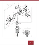
No. 39 in the attachment, I called it a filter. It is supposed to be reusable but I just replace it with a new one.There is a screen on that pump is a three hole plate on bottom of differential the Pto pump runs of a gear on the three point pump
Dman1981
Gold Member
- Joined
- Jul 28, 2023
- Messages
- 324
- Tractor
- Kubota bx2200
They do run off same sump a little tube form Pto pump to suction side
Of three point pump it is a cleanable screen no need to change it
I would still clean it
Of three point pump it is a cleanable screen no need to change it
I would still clean it
Dman1981
Gold Member
- Joined
- Jul 28, 2023
- Messages
- 324
- Tractor
- Kubota bx2200
I have seen screens that look ok but not have also had em when you rev them up would stop working also and implement drop create a vacuum from not enough oil
oldnslo
Super Member
DTJ,
Doe this problem only happen when you try to operate the PTO solenoid and does it stop as soon as you de-energize the PTO solenoid? If yes then I would look at the solenoid valve to confirm that it is shifting fully and not allowing oil to by-pass and escape elsewhere. Since no known schematic it is hard to determine where the oil is going but that would seem to be the common item in failure vs working system.
Doe this problem only happen when you try to operate the PTO solenoid and does it stop as soon as you de-energize the PTO solenoid? If yes then I would look at the solenoid valve to confirm that it is shifting fully and not allowing oil to by-pass and escape elsewhere. Since no known schematic it is hard to determine where the oil is going but that would seem to be the common item in failure vs working system.
Update: After more testing I have now tracked it down to the lift pump. Now I
m focused on the lift pump trying to figure it out, what could be wrong with it, while the tractor was running, I started turning the PTO on and off, while watching it. I now see what is happening. When I turn the PTO on the PTO clutch pack or the movement of the oil is pushing the pump control valve lever through the neutral position, just enough to stop the lift from raising, after taking my finger and pushing the lever forward and letting it pop back a few times, it seems to be working. Now it still moves when I turn the PTO on and off but it does not effect the flow of the fluid, out of the stand pipe, like before. Has anyone seen this before? Could it be a weak or broke spring or O-ring in the control valve?
In the attached video, on the right side of the main shaft, you can see the pump control valve lever moving back in forth when I turn the PTO on and off.
Thanks.
Attachments
Dman1981
Gold Member
- Joined
- Jul 28, 2023
- Messages
- 324
- Tractor
- Kubota bx2200
The screen is plugged