RedNeckGeek
Super Member
- Joined
- Jan 1, 2011
- Messages
- 8,388
- Location
- Butte County & Orcutt, California
- Tractor
- Kubota M62, Kubota L3240D HST (SOLD!), Kubota RTV900
The mag drill idea was a good one, but it turns out that the steel in the loader arms is too thin to allow a good magnetic grip and it isn't possible to get inside the box structure to slip in a back up plate. I ended up cutting the assembly apart and using a milling machine to bore the egged out holes for bushings. Here's how it went:
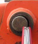
The rear pivot pins were originally 1.125" in diameter and were only slightly worn. The bores in the loader arms were egged out on each end by 0.060" or so, but the bosses in the side mounts had worn about 0.100" on each side. I have a hard time understanding how this could happen, as the pin is pinned in place so as not to rotate in the outer bosses. As such Kubota provided no grease fitting for the outer bosses; after all, they're not supposed to rotate. But the holes for the locking pins are significantly oversize for the locking bolts, and over the course of 2000 hours of operation, enough rotation in that unlubricated boss occurred to open them up. That slop put additional stress on the stiffener tube welds, which struggled harder to keep the arms parallel. When the welds failed, more side loads resulted in the bosses, creating a spiraling cycle of wear and weld cracking. It didn't help that much of the 600 hours I'd put on the tractor were spent shuttling landscaping materials around my hilly home site, most of it cutting across the slope face. That loading had caused the loader mounts to fail, and it became clear to me and others that had experienced the same issue that Kubota didn't plan for side loads and the FEL mounts, and now the pivots, were under engineered.
The most obvious problem is that neither the loader arm pivot bores nor the bores in the side plates were bushed, even though the front pivots (in the arms at least) were bushed. A contributing problem is that the pivot pin is allowed to rotate by the lock pins being lose in their holes, allowing the side plate pivots to wear. It was also apparent that the welds attaching the stiffener tube to the sides of the loader arms were subject to flex induced cracking, likely due to both the longitudinal seam on the tube and the location of the weld itself.
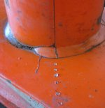
This photo shows a crack propagating from the end of the tube seam into the weld, then on into the loader arm itself. The seam acts as a stress riser, focusing loads into the toe of the weld and leading to failure. So in addition to enlarging the pivot bores for bushings, I'd need to re-engineer the stiffener tube attachment to keep the stresses away from the loader arm walls, channeling them to the outer edges of the arms.
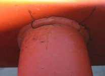
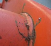
The welds attaching the stiffener tube to each loader arm were cracked, as were the loader arms themselves. Repairing the welds pretty much meant cutting all the way through the tube to get to the bottom of the cracks, so I just ended up cutting the stiffener tube off. That allowed me to get each loader arm onto the vertical mill to bore out the pin bosses. But the kerf of the cuts shortened the stiffener tube. I had some 0.125" 4130 plate on hand, left over from repairing the curl cylinder anchors on top of the loader arms. There was just enough to make up gussets for each end of the tube that would span from top to bottom of the arms, and an inch or so fore and aft of the tube wall. The scope of this job had quickly expanded far beyond what I'd anticipated, but my small shop was (just barely) equipped to handle the repairs.
In my mind the highest risk part of the repair was getting the pivot bores bored and bushed. The size of the arms was right at my limit to lift and accurately position them, and it seemed likely that the bores wouldn't end up exactly perpendicular to the arm. I was also concerned I'd have trouble locating the center of the bores because of the wear that had taken place. I chose to start with the bores in the side plates, hoping any experience gained there would help out when it came time to do the arms.
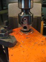
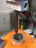
The side plate bore was 3.100" long, and based on the D.O.M. tube I'd be using for the bushings, I settled on a 1.334" OD and 1.140" ID for the bushings. It would have been nice to use 1.125" for the ID, but the tube wouldn't clean up at that diameter, and I had enough bar stock on hand to make up new pins. I supported the side plate on 1-2-3 blocks and clamped it onto the milling table. I indicated off the outside of the side plate bushings to find the bore center, then bored the upper bore. My boring bar wasn't long enough to reach the bottom bore, and the ones that were flexed so much that the resulting surface finish was unacceptable. To get around that problem I flipped the side plate over, then indicated off the ID of the freshly machined boss to locate center. That didn't give a perfectly alignment of the two bores, as I found later that the side plates were slightly bent. But it was close enough that the pins were a light drive fit, which was actually a good thing since they weren't supposed to pivot.
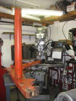
That left the pivots in the loader arms themselves. I hadn't quite made up my mind to separate both ends of the stiffener tube from the loader arms at this point, so the photo shows it still attached. I have a small lift table mounted on casters, and that proved invaluable in supporting and positioning the outer end of the arms. Again the 1-2-3 blocks were used to support the bore end of the arms, and I used a level on the arm to adjust the height of both the mill table and the lift table. I don't have a lot of faith trusting level for precision work like this, so I backed that up with a try square against the quill to double check. That long bore came out with surprisingly little diametrical difference between top and bottom, likely due to the light finishing cuts I used at the end.
View attachment 426115
I started with the side plate bushings, which were 1.085" long including a 0.100" thick flange on one end. The ID and OD were as mentioned above. Once turned, I held them in the milling vise and located the grease ports for drilling. A little time with a deburring tool and a sanding drum on the Dremel took care of any sharp edges. The loader arm bushes were turned and drilled in the same manner.
View attachment 426117 View attachment 426118
The tolerance variation in the bores and bushing IDs resulted in an interference fit of between 0.001" and 0.005", so my hopes of using a threaded rod and a couple of nuts to drive the bushings wasn't going to be strong enough. Years ago I'd purchased a 20 ton hydraulic press that in its former life had been used to cut masks for sandblasting letters into tombstones. I'd removed the large platen from the cylinder and rebuilt the hydraulics, and it was ready to go for this job. I used red 262 LocTite to secure the bushings into place, and found an appropriately sized bushing driver bushing on which to push. Again the lift table came in handy for handling the arms. I used a pair of pin punches, one in the bushing grease port or locking pin bore, another in the loader arm or side plate bore, to clock the bushings into alignment. The press has a fast rate low pressure pump for taking up slack, and I was able to use that for most of the installation. The high pressure pump came in handy to ensure that the short bushings were bottomed, and for the last inch or so of the 3" long bushings in the loader arms.
View attachment 426116 View attachment 426119
Next up was turning the pivot pins. The pins were turned from drops I'd picked up at a Reno, NV bridge fabricator. They're steel, and from the way they machined I'd guess they were low carbon A36. I'd hoped to turn them between centers, but one of the lathe dogs I had was too small and the other was too big, so I ended up just using the three jaw chuck to drive one end and a live center to support the other. I was able to control diameter variation to 0.001" over the 11" length needed to get the two 5.250" long pins, a find cut file providing the last couple thousandths of fine tuning. The pins were parted to length in the three jaw chuck, then cross drilled for the locking pins in the mill. I finished the locking pin bores with a 0.250" reamer, and planned to bore and bush the mating holes in the side plate bosses. The pins remained a light drive fit in the side plate bushings after installation. A trial fit of the side plates on the loader arms revealed that the side plate bushings prevented the loader arms from aligning properly, but a few passes with a flapper wheel on the angle grinder took care of the interference.
 View attachment 426121 View attachment 426120
Next I turned my attention back to the stiffener tube, and decided to remove it from the remaining loader arm. I used an abrasive cutoff wheel in an angle grinder for most of it. A long blade in a saws all finished up the places that couldn't be reached with the grinder. A thicker abrasive grinding wheel was used to chase the cracks out of the loader arms and smooth the inner sides so that the gusset plates would sit flat. E70S3 0.030" wire was used in a GMA (MIG) welder to fill the resulting grooves, which were then ground flush with the angle grounder.
View attachment 426126
A bit of cardboard was used to make a template for the gussets, which were then cut on a bandsaw. The gussets were centered over the holes in the loader arms and welded along both the outer edges and at the bottom of the stiffener tube stub on the under side. Once they cooled down, the side plates were mounted back onto the tractor, followed by the loader arms and finally the quick attach mount at the front. I used a pair of milk crates and some wooden shims to position the stiffener tube between the centers of the gussets, referring to photos taken prior to disassembly to determine the proper orientation for the hydraulic line brackets on the tube. I'd also prick punched the tube and loader arms with reference marks, but the marks were covered when the gussets were attached. The tube was then tacked at both ends, then welded into place. Pro welders often wear a short billed cap under their helmets, and I'd learned a long time ago that a good one will keep your hair from catching fire. What I didn't appreciate before this is that the bill will also keep sparks out of your ears. A red hot BB found its way inside my left ear, bouncing around until I heard a little phhhht sound, at which point my hearing on that side became a bit muffled. It's never been great, and I later learned that the ear drum would heal in a few weeks. I finished the rest of those welds with a set of ear muffs clamped firmly into place.
View attachment 426122 View attachment 426125 View attachment 426123 View attachment 426124
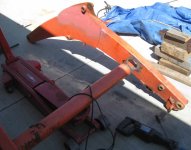
I'd taken the hydraulics off the loader arms to make the repairs, and at this point found the assembly too heavy to move with just my own strength. Once again the old Harbor Freight porta-power unit came to the rescue, forming a temporary replacement for the loader arm lift cylinder. That let me put the arms onto an old tarp spread out on a gravel pad where it would get a coat of paint. Sourcing the paint wasn't an easy job, as the Kubota dealer seemed no longer to supply the two part catalyzed version suitable for spray gun use. I'd used their paint to cover a fork lift attachment I'd fabricated a year before, and it was holding up much better than the Tractor Supply Krylon I'd used on the earlier loader arm repair. Fortunately the local automotive paint supplier was able to match the color from the plate that covers the hydraulic lines on the stiffener tube, the underside of which was largely unfaded. The paint looks so nice it puts the rest of the tractor to shame, but that's a whole 'nuther story.
View attachment 426127
It took another day or so to replace the hydraulic cylinders and lines and reattach the front links to the quick attach bracket. The biggest challenge was moving the hydraulic lines, which were mostly steel, and the heavy cylinders, into just the right positions. I'd taken many photos of how they were installed, and they were of great help, but that arm load of snakes was still took most of a day to get just right. I did get a little bit excited when I actuated the cylinders that curled the bucket and found that one side would fully extend before the other would move, but soon realized that was due to uneven friction in the seals that would easily be overcome once the bucket was once again attached. Also found that one of the short links between that cylinder and the quick attach had bent slightly, and that the bent one only worked at one location. That and the mislocating of the pin that the bucket level gauge connects to called for a do over before everything worked properly. I found that the new paint on the loader arms has eliminated the squeak when the level gauge moves, but I wonder how long that'll last. The last step was to grease all the pivots, but only a brief spurt from the grease gun was enough to empty it. I was really looking forward to wringing out a Lock'n'Lube tip on the gun, as it had gotten great reviews on Amazon.
But I did work the FEL enough to verify that all was working as it should. While parked on what passes for the most level spot on the driveway, measurements taken on either side of the bucket to ground differed only by 1/16" in a foot, good enough for tractoring and proof that all the work has been worthwhile.:cool2:

The rear pivot pins were originally 1.125" in diameter and were only slightly worn. The bores in the loader arms were egged out on each end by 0.060" or so, but the bosses in the side mounts had worn about 0.100" on each side. I have a hard time understanding how this could happen, as the pin is pinned in place so as not to rotate in the outer bosses. As such Kubota provided no grease fitting for the outer bosses; after all, they're not supposed to rotate. But the holes for the locking pins are significantly oversize for the locking bolts, and over the course of 2000 hours of operation, enough rotation in that unlubricated boss occurred to open them up. That slop put additional stress on the stiffener tube welds, which struggled harder to keep the arms parallel. When the welds failed, more side loads resulted in the bosses, creating a spiraling cycle of wear and weld cracking. It didn't help that much of the 600 hours I'd put on the tractor were spent shuttling landscaping materials around my hilly home site, most of it cutting across the slope face. That loading had caused the loader mounts to fail, and it became clear to me and others that had experienced the same issue that Kubota didn't plan for side loads and the FEL mounts, and now the pivots, were under engineered.
The most obvious problem is that neither the loader arm pivot bores nor the bores in the side plates were bushed, even though the front pivots (in the arms at least) were bushed. A contributing problem is that the pivot pin is allowed to rotate by the lock pins being lose in their holes, allowing the side plate pivots to wear. It was also apparent that the welds attaching the stiffener tube to the sides of the loader arms were subject to flex induced cracking, likely due to both the longitudinal seam on the tube and the location of the weld itself.

This photo shows a crack propagating from the end of the tube seam into the weld, then on into the loader arm itself. The seam acts as a stress riser, focusing loads into the toe of the weld and leading to failure. So in addition to enlarging the pivot bores for bushings, I'd need to re-engineer the stiffener tube attachment to keep the stresses away from the loader arm walls, channeling them to the outer edges of the arms.


The welds attaching the stiffener tube to each loader arm were cracked, as were the loader arms themselves. Repairing the welds pretty much meant cutting all the way through the tube to get to the bottom of the cracks, so I just ended up cutting the stiffener tube off. That allowed me to get each loader arm onto the vertical mill to bore out the pin bosses. But the kerf of the cuts shortened the stiffener tube. I had some 0.125" 4130 plate on hand, left over from repairing the curl cylinder anchors on top of the loader arms. There was just enough to make up gussets for each end of the tube that would span from top to bottom of the arms, and an inch or so fore and aft of the tube wall. The scope of this job had quickly expanded far beyond what I'd anticipated, but my small shop was (just barely) equipped to handle the repairs.
In my mind the highest risk part of the repair was getting the pivot bores bored and bushed. The size of the arms was right at my limit to lift and accurately position them, and it seemed likely that the bores wouldn't end up exactly perpendicular to the arm. I was also concerned I'd have trouble locating the center of the bores because of the wear that had taken place. I chose to start with the bores in the side plates, hoping any experience gained there would help out when it came time to do the arms.


The side plate bore was 3.100" long, and based on the D.O.M. tube I'd be using for the bushings, I settled on a 1.334" OD and 1.140" ID for the bushings. It would have been nice to use 1.125" for the ID, but the tube wouldn't clean up at that diameter, and I had enough bar stock on hand to make up new pins. I supported the side plate on 1-2-3 blocks and clamped it onto the milling table. I indicated off the outside of the side plate bushings to find the bore center, then bored the upper bore. My boring bar wasn't long enough to reach the bottom bore, and the ones that were flexed so much that the resulting surface finish was unacceptable. To get around that problem I flipped the side plate over, then indicated off the ID of the freshly machined boss to locate center. That didn't give a perfectly alignment of the two bores, as I found later that the side plates were slightly bent. But it was close enough that the pins were a light drive fit, which was actually a good thing since they weren't supposed to pivot.

That left the pivots in the loader arms themselves. I hadn't quite made up my mind to separate both ends of the stiffener tube from the loader arms at this point, so the photo shows it still attached. I have a small lift table mounted on casters, and that proved invaluable in supporting and positioning the outer end of the arms. Again the 1-2-3 blocks were used to support the bore end of the arms, and I used a level on the arm to adjust the height of both the mill table and the lift table. I don't have a lot of faith trusting level for precision work like this, so I backed that up with a try square against the quill to double check. That long bore came out with surprisingly little diametrical difference between top and bottom, likely due to the light finishing cuts I used at the end.
View attachment 426115
I started with the side plate bushings, which were 1.085" long including a 0.100" thick flange on one end. The ID and OD were as mentioned above. Once turned, I held them in the milling vise and located the grease ports for drilling. A little time with a deburring tool and a sanding drum on the Dremel took care of any sharp edges. The loader arm bushes were turned and drilled in the same manner.
View attachment 426117 View attachment 426118
The tolerance variation in the bores and bushing IDs resulted in an interference fit of between 0.001" and 0.005", so my hopes of using a threaded rod and a couple of nuts to drive the bushings wasn't going to be strong enough. Years ago I'd purchased a 20 ton hydraulic press that in its former life had been used to cut masks for sandblasting letters into tombstones. I'd removed the large platen from the cylinder and rebuilt the hydraulics, and it was ready to go for this job. I used red 262 LocTite to secure the bushings into place, and found an appropriately sized bushing driver bushing on which to push. Again the lift table came in handy for handling the arms. I used a pair of pin punches, one in the bushing grease port or locking pin bore, another in the loader arm or side plate bore, to clock the bushings into alignment. The press has a fast rate low pressure pump for taking up slack, and I was able to use that for most of the installation. The high pressure pump came in handy to ensure that the short bushings were bottomed, and for the last inch or so of the 3" long bushings in the loader arms.
View attachment 426116 View attachment 426119
Next up was turning the pivot pins. The pins were turned from drops I'd picked up at a Reno, NV bridge fabricator. They're steel, and from the way they machined I'd guess they were low carbon A36. I'd hoped to turn them between centers, but one of the lathe dogs I had was too small and the other was too big, so I ended up just using the three jaw chuck to drive one end and a live center to support the other. I was able to control diameter variation to 0.001" over the 11" length needed to get the two 5.250" long pins, a find cut file providing the last couple thousandths of fine tuning. The pins were parted to length in the three jaw chuck, then cross drilled for the locking pins in the mill. I finished the locking pin bores with a 0.250" reamer, and planned to bore and bush the mating holes in the side plate bosses. The pins remained a light drive fit in the side plate bushings after installation. A trial fit of the side plates on the loader arms revealed that the side plate bushings prevented the loader arms from aligning properly, but a few passes with a flapper wheel on the angle grinder took care of the interference.
 View attachment 426121 View attachment 426120
Next I turned my attention back to the stiffener tube, and decided to remove it from the remaining loader arm. I used an abrasive cutoff wheel in an angle grinder for most of it. A long blade in a saws all finished up the places that couldn't be reached with the grinder. A thicker abrasive grinding wheel was used to chase the cracks out of the loader arms and smooth the inner sides so that the gusset plates would sit flat. E70S3 0.030" wire was used in a GMA (MIG) welder to fill the resulting grooves, which were then ground flush with the angle grounder.
View attachment 426126
A bit of cardboard was used to make a template for the gussets, which were then cut on a bandsaw. The gussets were centered over the holes in the loader arms and welded along both the outer edges and at the bottom of the stiffener tube stub on the under side. Once they cooled down, the side plates were mounted back onto the tractor, followed by the loader arms and finally the quick attach mount at the front. I used a pair of milk crates and some wooden shims to position the stiffener tube between the centers of the gussets, referring to photos taken prior to disassembly to determine the proper orientation for the hydraulic line brackets on the tube. I'd also prick punched the tube and loader arms with reference marks, but the marks were covered when the gussets were attached. The tube was then tacked at both ends, then welded into place. Pro welders often wear a short billed cap under their helmets, and I'd learned a long time ago that a good one will keep your hair from catching fire. What I didn't appreciate before this is that the bill will also keep sparks out of your ears. A red hot BB found its way inside my left ear, bouncing around until I heard a little phhhht sound, at which point my hearing on that side became a bit muffled. It's never been great, and I later learned that the ear drum would heal in a few weeks. I finished the rest of those welds with a set of ear muffs clamped firmly into place.
View attachment 426122 View attachment 426125 View attachment 426123 View attachment 426124
I'd taken the hydraulics off the loader arms to make the repairs, and at this point found the assembly too heavy to move with just my own strength. Once again the old Harbor Freight porta-power unit came to the rescue, forming a temporary replacement for the loader arm lift cylinder. That let me put the arms onto an old tarp spread out on a gravel pad where it would get a coat of paint. Sourcing the paint wasn't an easy job, as the Kubota dealer seemed no longer to supply the two part catalyzed version suitable for spray gun use. I'd used their paint to cover a fork lift attachment I'd fabricated a year before, and it was holding up much better than the Tractor Supply Krylon I'd used on the earlier loader arm repair. Fortunately the local automotive paint supplier was able to match the color from the plate that covers the hydraulic lines on the stiffener tube, the underside of which was largely unfaded. The paint looks so nice it puts the rest of the tractor to shame, but that's a whole 'nuther story.
View attachment 426127
It took another day or so to replace the hydraulic cylinders and lines and reattach the front links to the quick attach bracket. The biggest challenge was moving the hydraulic lines, which were mostly steel, and the heavy cylinders, into just the right positions. I'd taken many photos of how they were installed, and they were of great help, but that arm load of snakes was still took most of a day to get just right. I did get a little bit excited when I actuated the cylinders that curled the bucket and found that one side would fully extend before the other would move, but soon realized that was due to uneven friction in the seals that would easily be overcome once the bucket was once again attached. Also found that one of the short links between that cylinder and the quick attach had bent slightly, and that the bent one only worked at one location. That and the mislocating of the pin that the bucket level gauge connects to called for a do over before everything worked properly. I found that the new paint on the loader arms has eliminated the squeak when the level gauge moves, but I wonder how long that'll last. The last step was to grease all the pivots, but only a brief spurt from the grease gun was enough to empty it. I was really looking forward to wringing out a Lock'n'Lube tip on the gun, as it had gotten great reviews on Amazon.
But I did work the FEL enough to verify that all was working as it should. While parked on what passes for the most level spot on the driveway, measurements taken on either side of the bucket to ground differed only by 1/16" in a foot, good enough for tractoring and proof that all the work has been worthwhile.:cool2: