Jimmy,
Jimmyb33 said:
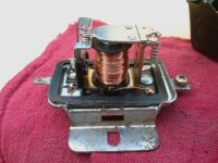
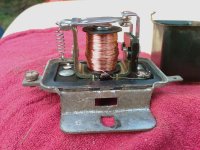
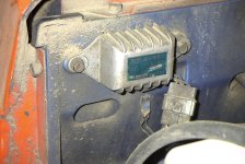
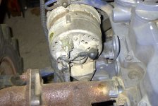
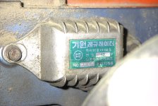
ok.. I was able to get some pics of the "regulator". I also was trying to trace the lines out of the original regulator... didn't take long for me to realize that I'm not too good with electrical stuff.
Just because you couldn't trace some wires in a bundle in impossible to get at places... doesn't mean you are not too good with electrical stuff. You have made more progress here than lots of folks I know would have.
Jimmyb33 said:
I tried to do connectivity test on some of the wires out of the regulator and kept getting "everything is connected to everything" else results.
This is not surprising, especially if you had the ohm meter on something higher than the minimum scale. The original regulator is solid state and everything connected to everything is sort of expected. If your meter had a diode setting, that is the only one that would have any meaning.
Jimmyb33 said:
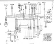
I was able to check for voltage on the original regulator. The electrical diagram attached shows the I get 12v out of the blue and red wires when the key is turned on. I don't get any voltage out of any other connections at the regulator.
Did you put the voltage readings on the schematic you posted, along with the wire colors? I spent some time tracing the wires in the schematic... either the color coding is wrong, the schematic is wrong, or the wires change color between pt A and pt B.

Makes it difficult to sort out.
Jimmyb33 said:
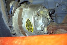
There is no voltage on the "field" connection on the alternator.
I didn't think there would be, thanks for verifying this.
Thanks for the pictures of the regulator insides. It tells me the unit is in good shape, the contacts look good, no sign of corrosion or pitting. When you put the cover back on, make sure it is tight the gasket is sealed well. I would also gently clean up the back side where the two wire wound resistors are.
I think the 12v readings you got on the Original Regulator are the battery input, red wire, and the field output, blue wire. I suspect the yellow wire goes to the alternator warning light on the dash, so I am a little surprised you didn't have 12v there as well. Although, the blue wire could be the lamp with the yellow for the field. Is there any sign of cut wires around the alternator, if so, what color are they? I would be looking for a blue or yellow wire. Is there a connector tucked away somewhere nearby? Since we don't know were these wires go.. I suggest we don't mess with this regulator, yet.
Now the question is... How lucky do you feel??
If it was me... at this point I would get:
- A friend for another set of hands who is comfortable with electricity, running motors and reading meters.
- A second volt meter.
- A length of thin wire, 24 gauge or smaller, to get from the battery to the IGN connection on the "new" Regulator. Remember, a 28 gauge wire is smaller, and for this test better, than a 24 gauge wire. The safest would be to get a small fuse, 2 amp or so, and put that in series with this wire, as close to the battery as you can. Most folks don't have a fuse holder laying around and I wouldn't bother making a trip to Radio Shack or similar place just to get one.
I would:
- Put one meter across the battery to monitor its voltage.
- Put the other meter from the "Field" connection on the alternator to ground. This would be to monitor if any voltage is getting to the alternator.
- Connect one end of the length of wire to the + side of the battery. On the end of the wire that is free, strip off very little of the insulation. This is to minimize the change of the battery being shorted to ground. This is why I suggested a small wire, if it does get shorted, the wire will act as a fuse. The worse that will happen is the wire gets hot where you are holding it. Remember to keep this wire away from ANYTHING on the motor that might move. Tape or ty-raps are your friend here.
- Start the tractor, bring engine RPM to 1400 or so, no need for anything higher. Monitor voltage at battery and at "Field" connection on the alternator. Take the wire and touch it to the IGN connection on the regulator. Just touch it for a second or two.. just enough to see if you get any voltage at the "Field" connection on the alternator. Be aware, if things are working correctly, there is a good chance there will be some sparks when you touch your wire to the IGN terminal, this will actually be a good sign. If you do get voltage at the field connection, then I would try again, slightly longer, and see if the voltage increased on the battery. You might also hear a slight change in the tone of the engine if the alternator does put out voltage as it will be trying to charge the battery.
If you have ANY questions about this procedure... post them before you start.
Good luck.. let us know the results.