Look what I got for $1700

   / Look what I got for $1700 #11  
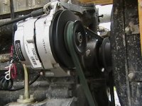
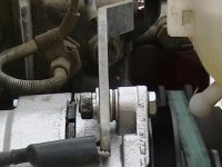
The OEM alternators are only ~14 amp. Won't even keep up with your headlights. Ask me how I know this.. The Delco 10 Si or 12 Si are direct shoe-in replacements - even use the same pulley. The only real mod you will have to do is get a different length fan belt and insert a couple of spacer washers for the adjusting arm. I went with the segmented belt from Harbor Freight - I will never have to replace it again.
I went with the 12Si 72 amp alternator because I use electric winches, powerful lights, and a 110v inverter.

Actually, what RonMar said is true If all you need the battery for is starting the engine. Just use the alternator to keep the belt tight.
 

Attachments

  • New alt. 008.jpg
    New alt. 008.jpg
    112.1 KB · Views: 324
  • New alt. 009.jpg
    New alt. 009.jpg
    109.1 KB · Views: 261
   / Look what I got for $1700 #12  
14A of current at 14V is enough to power 200W of lights... I think my headlights on mine are only about 55W each...

I didn't know the delco 10 or 12 was a direct bolt in for the jinma, that is good info to know, thanks.
 
   / Look what I got for $1700 #13  
14A of current at 14V is enough to power 200W of lights... I think my headlights on mine are only about 55W each...
Well, the voltage regulator cuts the alternator output down to 12v for lighting and accessories. So that leaves ~168w of power to be consumed by headlights, side lights, brake lights, tail lights, instrument lighting, et cetera. And if your headlights are still original, they're probably 35w. Folks early on tried replacing the rather dim OE with 55w aftermarket, and quickly ran into alternator limitations.

//greg//
 
   / Look what I got for $1700 #14  
Yes, exactly what everyone has said, Congratulations on a super buy. And I've installed the 10SI three wire alternater on my JM354 and it had to have the wider pulley and also I had to get the special nut for the wide pulley. The 10SI cost me $16 at the wrecking yard and has been the best invest so far, I also installed a group 31 battery $120 from O'riellys Auto supply (Used to be Shucks). bjr
 
   / Look what I got for $1700 #15  
Well, the voltage regulator cuts the alternator output down to 12v for lighting and accessories. So that leaves ~168w of power to be consumed by headlights, side lights, brake lights, tail lights, instrument lighting, et cetera. And if your headlights are still original, they're probably 35w. Folks early on tried replacing the rather dim OE with 55w aftermarket, and quickly ran into alternator limitations.

//greg//

UH Greg, if the voltage regulator cut the voltage down to 12V, the battery would never reach a full charge... Bare minimum float voltage to maintain a lead acid battery at full charge is around 13.2V

A proper voltage out of an alternator is 14.5V +/- .5V. Mine is barely acceptable at it's output. My 284 running at 1200 RPM delivers 13.9 VDC at the battery. This was with all the lights off. Under the same conditions, with all the lights(head, running and rear work light) switched on, the voltage actually increased slightly to 13.95 VDC at the battery. If the voltage regulator is working properly, The voltage should stay fairly constant with load and RPM changes up to it's current limit.
 
   / Look what I got for $1700 #16  
UH Greg, if the voltage regulator cut the voltage down to 12V, .the battery would never reach a full charge.
Check your wiring diagram Ron, not all battery charge circuits include the voltage regulator (VR). Some are on a separate circuit that is independent of the VR. At least it did on the 4 Chinese tractors that I owned. That said, they were all 3-wire alternators (external VR). What follows is not necessarily applicable to 1-wire alternators or conversions.

Take this Jinma 200 Series diagram for example; the + post on 3-wire Alternator (5) sends unregulated voltage on wire #4 to the ammeter (12). At this point it's also paralleled to the keyswitch (13) on wire #5. When the keyswitch is placed in the RUN position, the ammeter then sends said voltage via wire #3 to/through the system fuse - then onward to the starter solenoid (6) on wire #2. From there it rides the battery cable back to the + post on the battery. This is charging voltage, no VR in the circuit. Any "regulation" done is a feedback function of the battery charge state; low charge/high voltage, normal charge/maintenance voltage.

FWIW, unregulated voltage also travels wire #8 between the alternator and the VR. From there wire #7 feeds regulated voltage to the rest of the circuits in the fuse panel.

Assuming your 284 conforms to the above diagram, your symptoms describe both regulated and unregulated voltage. But since accurate voltage readings are dependent upon a good ground, you might want to clean both ends of the battery ground cable. You've been around long enough to know to clean the paint/rust under the ground lug on the frame. And if there's any white stuff showing between the cable strands and the insulation, it might be time to replace the cable as well. If none of that returns your voltage reading to normal, it might be time to start thinking new alternator.

//greg//
 

Attachments

  • 200 series wiring.jpg
    200 series wiring.jpg
    87 KB · Views: 1,215
Last edited:
   / Look what I got for $1700 #17  
Wire 7 is a sense line, the regulator senses this point to control current in the field windings of the alternator. More current = stronger field = higher voltage. Less current = weaker field = lower voltage. The output of the alternator is wire 4.

If the voltage on the + terminal of the ammeter is higher than the battery voltage, the ammeter will show charging. If the voltage is lower, the ammeter will show discharge.

The point is that the regulator sees to it that it maintains the alternator output at a regulated level. The regulator regulates current in the alternator windings, it does not output a regulated voltage to anything.
 
   / Look what I got for $1700 #18  
I see. Perhaps I misinterpreted the wiring diagram. I was keying off the fact that wires #2 and #3 do not physically feed the fuse panel bridge. Rather, they simply connect the ammeter and the battery via the 30A system fuse. So going by your asserting, then it's wire #6 that actually feeds the bridge. Wire #7 is then paralleled off for purposes of VR feedback (sensing) to the alternator. Is that more in line with how you see it?

//greg//
 
   / Look what I got for $1700 #19  
I see. Perhaps I misinterpreted the wiring diagram. I was keying off the fact that wires #2 and #3 do not physically feed the fuse panel bridge. Rather, they simply connect the ammeter and the battery via the 30A system fuse. So going by your asserting, then it's wire #6 that actually feeds the bridge. Wire #7 is then paralleled off for purposes of VR feedback (sensing) to the alternator. Is that more in line with how you see it?

//greg//

Yes. Wire 5 gets connected to wire 6 via the ignition switch to power up the rest of the system.
 
   / Look what I got for $1700 #20  
Thank you for the edification. I've apparently been misinterpreting that diagram for quite a while now.

//greg//
 
 
Top