Mf 135 auxillary hydraulic control

   / Mf 135 auxillary hydraulic control #11  
Yes,, the single hydraulic hose comes from the left side to the auxillary valve. Then when I decrease the hydraulic pressure the weight of the loader itself pushes the hydraulic fluid back Into the tractor. As I said beforehand just like a tipping trailer.

I've been giving your situation more thought and I think adding a divirter valve in place of the transfer cover would not be a major difference than adding a massey two spool to the tractor.

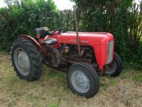
On my 135, I have a two spool valve. The left hand lever controls the three point. I have to pull the lever toward the seat and lock it in with the detent to control the three point operation from the position or draft levers on the right hand side of the seat. To use the auxiliary circut, I must move the left hand lever on the valve to its center position to isolate the three point, move the position lever on the right hand side of the seat to the constant pumping position, then use the right hand lever on the auxiliary valve to raise and lower the auxiliary cylinder. (The two spool valve must have an extra return port back to the differential case to allow this to work.) If I leave the left hand lever pulled toward the seat when operating the auxiliary circut the three point goes up and down such as you have experienced. I can center the right hand lever and use the left hand lever to raise the three point at this time but cannot lower it without using the position lever on the right hand of the seat. Its a bit confusing and awkward but you get use to it after a while.

So, my thinking right now if the divirter valve is easilly switched, it would be the same and a whole lot cheaper. the one thing that comes to mind though is to lower the auxiliary cylinder you would still be using the position lever on the side of the seat. On my 135, I can raise and lower the auxiliary circut without touching the position lever and leaving it in the constant pumping position. It seem to me that you could do without the single spool valve in the circut and control the up and down of the auxiliary cylinder with the position lever unless you would and a return line back to the differential case.

I don't know why, but in some ways it seems these older Massey's weren't that sofisticated in the auxiliary hydraulics as newer tractors. My opinion of course. I'm sure someone more knowledgable may disaggree since the invention of the Ferguson system.

Hopes this helps and does not make it more confusing.
good luck

namyessam
 
   / Mf 135 auxillary hydraulic control
  • Thread Starter
#12  
Thanks a lot for that reply, it has made me understood a bit more but what I'm
Getting at is how does a diverter valve fit on the tractor to stop the 3 p.t. I like to
Understand everything before I install it.
Thanks in advance
 
   / Mf 135 auxillary hydraulic control #13  
Thanks a lot for that reply, it has made me understood a bit more but what I'm
Getting at is how does a diverter valve fit on the tractor to stop the 3 p.t. I like to
Understand everything before I install it.
Thanks in advance

From what I have seen on this forum, the diverter valve is bolted to the top of the lift cover in front of the seat in place of the transfer cover. There are three O-rings under it to create the seal. It is the rectangular plate about 2 inches by 4 inches. The high pressure oil from the pump comes up to this area by a tube sealed with O-rings. The oil from the pump will enter the diverter valve and will be directed to the auxiliary circuit or to the three point which ever way it is switched.

To raise the loader You will need to switch the diverter to the auxiliary circuit and pull the position lever back, then pull your auxiliary valve to raise the loader. ( after rethinking my previous post, you will need to keep this valve in the circuit.) release your auxiliary valve, this will isolate the auxiliary circuit and keep the loader raised. you will need to push the position lever forward then switch the diverter valve then pull the position lever back to raise the three point with the loader raised.

To lower, Diverter valve in the three point position. push the position lever forward and three point will lower. Switch the diverter valve to auxiliary, then pull the auxiliary valve back and the loader should lower.

namyessam
 
   / Mf 135 auxillary hydraulic control
  • Thread Starter
#14  
Hi, I'm really sorry to be wasting so much of your time
By the way! You know the pipe you talked about, is it already installed so that all I have to do is buy the diverter and bolt it to the top of the tank
 
   / Mf 135 auxillary hydraulic control #15  
Hi, I'm really sorry to be wasting so much of your time
By the way! You know the pipe you talked about, is it already installed so that all I have to do is buy the diverter and bolt it to the top of tank.

The tube I am speaking of is on the inside of the differential case feeding high pressure oil from the pump to the three point control valve. The junction of these two lines is under the small cover on top of the lift cover bolted to the differential housing. The diverter needs to be installed in this location so you can redirect oil from the three point circuit to the auxiliary circuit. If you hook the diverter to the pipe you have installed into the top cover you will not stop the flow of oil to the three point. That is what is what you need to independently control the back loader and the three point hitch. I believe this is correct. Can someone else confirm my instructions. Don't be afraid to correct me. I'm learning also and this is what I have learned from my tractor.
 
   / Mf 135 auxillary hydraulic control
  • Thread Starter
#16  
Oh right thanks that would make sense. Would I need a diverter made to fit the 135 or would I be alright in using a universal hydraulic diverter. Thanks a lot!
 
   / Mf 135 auxillary hydraulic control #17  
Oh right thanks that would make sense. Would I need a diverter made to fit the 135 or would I be alright in using a universal hydraulic diverter. Thanks a lot!

You would need one designed to fit a Massey 135 so it would match the bolt pattern and the hydraulic port positioning. There are one's available if you Google, Massey auxiliary hydraulic system
 
   / Mf 135 auxillary hydraulic control #18  
--------------------------------------------------------------------------------

G'day dexter9.

To do what you want to do you will need :
A hydraulic selector valve, buy the PUSH/ PULL TYPE ,this valve is made to fit Massey tractors only.
A dual hydraulic spool with both spools being SINGLE ACTINGl.
Hoses. I use 3/8 inch hose ,no smaller.
The dual spool and selector valve can be bought from ,
SSB Farm Tractor Parts, Tractor Manuals, Implements, Loaders & Antique Toy Pedal Tractors or Sparex ,bareco,vapormatic etc.
The hoses can be either purchased premade or made to order locally.

Under the seat there is a transfer cap ,it is on the lift cover, that is the hydraulic cover that the seat fits onto,front right hand corner,it is about 3 inches by two inches held on by two bolts.
Important : Before you remove the cap lower the hydraulic linkage ALL THE WAY DOWN
This will drain all the oil from the lift system and avoid injury also minimising the mess on the shop floor.

Remove the cap and install the selector valve, when you remove the cap there is a Hydraulic stand pipe which sticks out of the lift cover replace the "O" ring , if the standpipe comes out of the pump remove the sideplate ,the one with the transmission dipstick lower the standpipe and with your left hand guide the pipe into the hole in the hydraulic pump,if you want to make sure it is in the correct spot,PULL OUT THE ENGINE STOP and place the lift levers ,draft in the up position and position in the transport position then crank the engine a little bit say two turns of the engine, if you get oil on the shed floor this will tell you two things,one the pipe is in the correct spot and two you cranked the engine to long.

Next fit the NEW SELECTOR VALVE,the outlet of the valve is 3/8 bsp thread .
Mount the dual spool valve the same place as you would when fitting a front end loader,somewhere comfortable to operate,when it is mounted in your place of choice,connect the supply hose from the selector valve that you fitted,(the one under the seat) to the SUPPLY on the spool valve.

The return hose can either be fitted to the transmission filler cap or under the seat ,left hand side about where the FRONT seat mounting stud is ,you will find a 3/8 inch bsp allen grub screw/plug in the hole,remove the plug and fit the return hose from the return on the spool valve it will be better if you install a 90 degree elbow into the tractor ,it keeps the hose neat.


The SELECTOR valve under the seat will now when operated give you hydraulic supply to the spool ,there will be no need to fiddle with linkage controls etc ,all can be done using the dual spool valve.

To return the hydraulics to standard operation that is using the tractor controls place the hydraulic spool valve in the IN position .

To use the external hydraulic controls pull the selector valve OUT,SET THE HYDRAULIC LEVERS IN ,one DRAFT all the way up
and POSITION control lever in TRANSPORT, THIS WILL NOW GIVE YOU CONTROL OF THE HYDRAULIC RAM ON THE LOADER INCLUDING THE LIFT ARMS.
Example to raise AND lower the linkage operate the lever and the linkage will be raised and lowered as you would using the hydraulic control quadrant on the tractor the only thing it won,t do is give you draft operation it will only raise and lower the same way as when you are using the POSITION Control lever.
The other lever will give you control of the loader ram,example( depending how you connect the hydraulic hose) pull the spool lever towards you and the ram will extend ,push it forward and the ram will retract.


You will find it a lot easier to fit quick disconnect couplings to the hose ends ,it is much easier than unscrewing hoses and a lot less messier,just remember if you do ,before Disconnecting a coupling lower the linkage to the ground ,make it safe by operating ALL levers with the engine stopped this will make sure there is no trapped hydraulic pressure,.
If you were to disconnect a hose with pressure still in the hose the coupling will be under pressure and you will find that when you come to reconnect the hose it will not reconnect because the pressure is holding the coupling valve closed,if you find yourself in this position ,get a bolt that fits inside the coupling ,put the bolt in the end of the coupling ,wrap a rag/cloth around the whole thing and give the head of the bolt a reasonable tap either on a piece of wood or with a hammer ,not to violent you are only pushing the small non return valve ball back to let the trapped oil out.
That is all you need to do.
Easy.
Happy Days.
Hutch.

p.s. I have copied and modified this reply from another site that I answered a similar question to.
 
   / Mf 135 auxillary hydraulic control #19  
Shona13, when using the aux' hyd's, the position control lever is not put in transport position. It is pushed over so it clears the stop for transport position and then pushed further back into the constant pumping position. When in constant pumping, you don't want the 3 pt. lifted up higher than the transport position. That's why the transport stop is there. The aux. hyd's sometimes work with the position control in transport position but it should be pushed further back into constant pumping to get max. flow. I find if I have the 3 pt. about 3/4 of the way up it doesn't slow down the aux. flow that is slow to begin with.

There is a way to use the draft control lever to operate a single acting cylinder on a 135. Unfortunately if you need to use the 3 pt., you can't use them both at the same time. I think it explains it in the owners manual but there is also an aux. hydraulics manual for the 100 series tractors that explains in detail hooking up the aux. valve(s). There are several different styles of diverter/spool valves from basic to relatively complex. The one on my 135 has 2 spool valves very similar to namyessam. 1 is locked back so the side 3 pt. controls work and to use the aux. the 3 pt. spool is put in neutral and the side controls put in constant pumping. Then the other spool controls aux. cylinders. On my tractor the aux. spool is tied into a separate 2 spool valve mounted on the front end loader. The diverter/spool valve(s) I have also has a knob that can be adjusted for use with single acting or double acting cylinders. It seems extremely complicated if you're brand new to it. The aux. hyd's on the 100 series aren't the most sophisticated but the advanced Ferguson System on them is the best 3 pt. mechanism ever designed and is quite complex. A big reason MF 100 series are still so popular. One of the complaints with it though is that the 3 pt. will creep down unless the pump and side controls are in operation. Especially if you have a heavier implement on the the 3 pt. and are using the aux. hyd's, the 3 pt. will creep down. I don't use my loader too much since I have a skid steer but if I need to use the loader for a while, I won't have an implement on the 3 pt. It's kind of a pain to have to keep raising the implement. Some people have used chains to stop the 3 pt. from creeping. A front pump is real nice but costs a bunch to do. I think your best bet is to find an MF dealer/mechanic that has has been around for a while to explain it to you in person. It can be very hard to understand a bunch of typed words.
 
   / Mf 135 auxillary hydraulic control #20  
My old Massey 35 had a diverter valve in front of the seat with 3 positions : back outlet (mostly for my trailer), rockshaft, loader (all single action). Of course, only one at a time. This made it difficult for example to lower the loader to avoid a tree without dropping the implement on the 3 points. Still worked great for 13 years.
 

Attachments

  • DSCF0148 (Copier).JPG
    DSCF0148 (Copier).JPG
    128.4 KB · Views: 1,241
  • DSCF1207 [Résolution de l'écran].JPG
    DSCF1207 [Résolution de l'écran].JPG
    442.8 KB · Views: 5,090
 
Top