More Foaming Hydraulic issues. JM 284

   / More Foaming Hydraulic issues. JM 284
  • Thread Starter
#11  
Chip thank you very much!

I had one with a cracked casting under seat when new as well! damaged in transit/shipping. it took me a while to find it as it was closed up but was enough to let air in.

I'll be putting the pump on in the morning with that info.

yes the rebuilding issues may be related to the pump design which has no bearings. only smooth surface with oil film under pressure and the drive gear teeth can wear the surface if the W rings are too fat and almost looks as if they machine these to fit for XXX dim W rings.

anyhow thanks again

Mark M
 
   / More Foaming Hydraulic issues. JM 284
  • Thread Starter
#12  
hi all:

new update.
I managed to remember the camera and took a of of pics and will post them on photobucket with links in this thread later. (have to work tonight.)

short version

I got the OLD pump apart, new seals and still when tight would not rotate. SO put in new pump bearings and pump drive shaft. every thing works so far no foaming, got to fully re-assemble seat tuck in wires & hoses add tie wraps back onto couplers ect.

OK anyhow long version

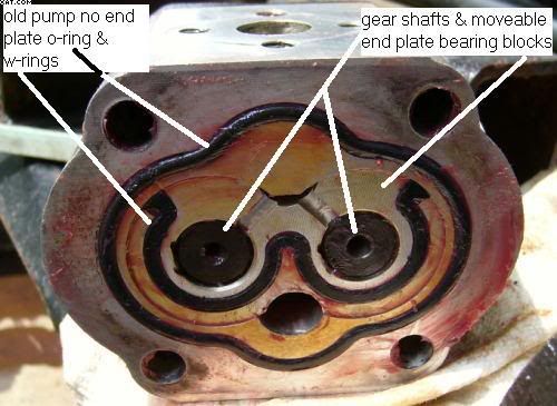
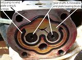
after I got pump & spare kit from Jerry down in TX @ Affordable Tractor I went at the OLD pump first, put in the kit only to have the pump lock up when tight, it would spin freely when no seal pressure was on the pump of course it leaks like a sieve like that but when tight it wouldn't rotate or let motor turn over even. closer inspection & taking pump 100% apart found that the gear drive and the gear drive end bearing/floating plates were slightly scored and so was one bearing surface inside the pump gear shaft bearing surface. these were all cleaned up to near polished surface at work. looked great & performed well. but only when the pump was left LOOSE. what I found was that the new pump kit was pushing the end plates IN and compressing them onto the PUMP GEARS which would lock them in place. no fix for this yeat but what I did was to use the new seals and tighten the pump down together and added 2 3/8" long bolts to the empty 2 holes and simply bolted it all tight to let the seals get compressed hopefully relieving the seal compression problem when if I ever need the pump...


since I was putting in the NEW pump I put in a NEW pump drive shaft as well. when pulling this apart I needed direction and got a little help from CHIP over at Bolton but he was only able to confirm that it came out the back face side were the pump mounts & couldn't remember what all had to come out.

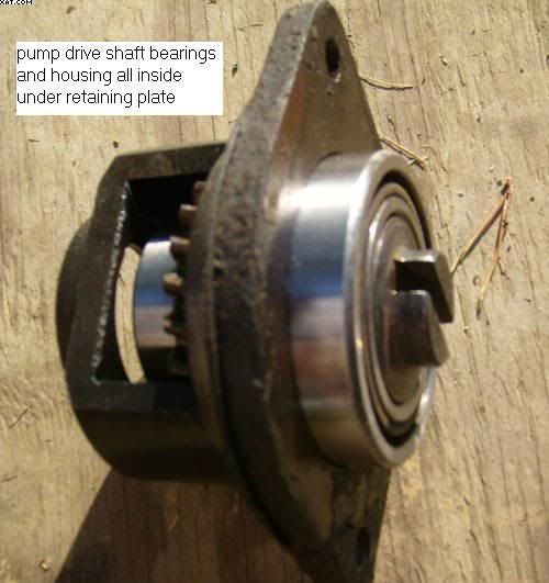
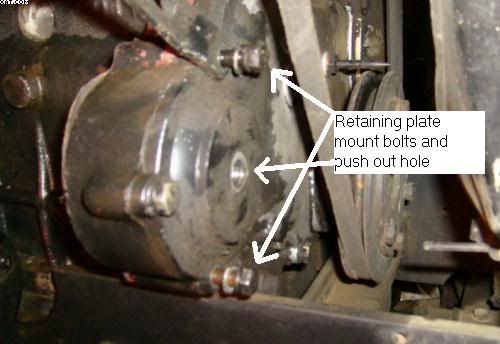
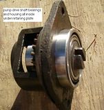
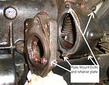
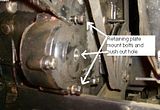
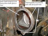
SO I went after it, the PUMP is held onto a moderately heavy plate using 2 of the 4 pump bolts the other 2 bolts simply hold the pump parts all together. This PLATE is held onto the Engine by 2 bolts that goes in from the front of the engine gear train cover all the way through and into this moderately heavy plate.. the top bolt holds the Alternator Bracket and the Bottom bolt is bottom center of the cam/injection pump/hyd pump drive gear cover. then there is a 1.5 x ~14 MM thread pitch bolt which looks like a Oil Drain Bolt. I removed that bolt which then lets you gain access to the back side of the Hyd Pump Drive Shaft. It has to be Pushed Out probably using that threaded hole if you can find the proper bolt or all thread rod. It can only be about 5" long but would be nice to find one longer if need be and cut it off so that it would make a great little tool. I ended up using a punch and pry bar as the radiator is too close to swing a hammer. but only AFTER that heavy plate is removed as that retains the shaft & bearings & gear that drives the pump.

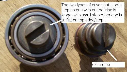
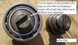
I ended up popping the outer race off one of the bearings as there is no good way to remove them off the shaft, the gear comes off easily after the bearings are out of way. also there are 2 different types of shafts. Jerry sent me both shafts as I didn't know WHICH one I had but after seeing both and what I had you can tell them apart while still in the tractor but you need to get in there to really see and have hyd pump removed too. the SHORT shaft is flat on front and the longer one has an extra step cut into the front face.

anyhow every thing was re-assembled and the 2 bolt pump intake flange was left loose and the hyd tank was filled all way up, I took the hyd vent plug put that in and put 5~10 lbs of pressure of air into the pump vent pushing hyd fluid down the pump suction line and pushing the air out of the lose connection pre-filling the pump suction line and pump to prevent more air sucking and or more pump problems... NOTE: I held open end of the air gauge/hose onto the vent tube, not tight inside was <u> <b>low pressure</u> </b> so as to not blow anything up. all worked out well and I tightened the pump suction line 2 bolt flange & fired it up. all was well very little to no foaming (entrapped air in lines & cylinders only) while cycling FEL & 3 pt lift to remove air out of those. so far all seems WELL :)

will add pics later.

edit in pics click pic to view full size from photo bucket ~40 k each down sized


Mark M
 
Last edited:
   / More Foaming Hydraulic issues. JM 284 #13  
Sounds to me like a case of chinese 'hand-fit' non interchangeable / assembly line parts...

Soundguy


SPIKER said:
hi guys:

so far the old pump still locks up but with further inspection I can see why. what is happeneing is the new W rings are much fatter than the old ones were I ASSUMED that it was just fact old ones were compressed. but it appears that the milling on my pump bearing parts was not as deep as the new ones must be as there is almost 1/8" of the W rings sticking out. what effect this has on the pump is to compress the W rings actually pushes the two (2 ) bearing halves in towards each and the pump gears are there and the sides actually rub metal to metal on the gear teeth edge surface. normally this is all in good oil bath and makes little or no contact under normal pump pressure. BUT with the FAT o/W rings these two parts are squeezing the pump drive gears so hard that the pump won't budge and has galled the aluminum slightly (I fixed this using granite surface block and 320 sand paper to flatten & polish the galled surfaces back to good smooth surface.) also was able to use high speed scotch brite pad to clean up the gear teeth matting flange. every thing is back to spinning smooth & free when un-compressed. but under compression I get same problem, too fat of w-rings. I'm going to try the old ones back in there later as for now I assembled the pump using all 4 bolt holes under good tight condition for a few days to see if the pump will loosen up a bit ??

so far no one has stepped up to say yes or no, on having to pull the front cover off engine to change out the pump drive shaft/gear... any one do this yet?

thanks mark
 
   / More Foaming Hydraulic issues. JM 284
  • Thread Starter
#14  
Soundguy: not sure if the thicker W rings are something that is FIXED or was made by a different mfg over there or if the new W rings are simply a different material than the old ones? it may be that the KIT I got was/is for a newer pump/tractor as mine is 2002. anyhow it (the new pump) appears to have fixed the foaming issues. I did not try the OLD W-Rings in the old pump with the new shaft seal but may work just fine with those as the outer O-Rings are what keeps pumps from leaking/sucking air the W-Rings simply keeps/directs pressurized fluid closer to the pump gear shafts to lube them under pressure as there are milled slots/groves that bring the fluid back past from the pressure side of the gears through the bearing area & back around via W-Rings and into the end suction side of the pump if you look at the 2nd from last pic above you can see the port on the bottom is the pressure OUTLET port, the W ring and the outer O ring keeps pressurized fluid from going back that way, there is a small port at the top of the W that is on the suction side and 2 groves (white lines cover one a little but other one is very visible) where the now under suction fluid passes back into the intake port area. the fluid flows from the side of the gears under the gear flange/edge around the gear shaft & aluminum bearing surface and out into the cavity of the W ring and then back into the suction port.

the problem I'm describing is that the W-rings on each end of pump are fat which means that the pump side bearings that hold the gear's bearing shaft are pushing IN towards the center and the smooth mating surface of the pump gears and aluminum bearing blocks are too tight to let the pump start to turn which means no fluid for lubing all these bearing surfaces and no turning...

anyhow hope that helps

Mark M
 
   / More Foaming Hydraulic issues. JM 284 #15  
Hmm.. did you motice any difference in machine on the pump castings / heads? ( or.. I'm guessing yuo didn't actually pull the new one apart to check.. I don't blame you if you didn't.. I probably wouldn't have )

It would be interesting to check one day. if you ever have to work on the new pump.. you might check it's facings against the old one to see if it was merely a seal difference.. or machining..e tc..

either way.. glad ya got ti fixed..

Soundguy
 
   / More Foaming Hydraulic issues. JM 284
  • Thread Starter
#16  
soundguy:

yes I left the NEW pump un-touched and just put it in... HOPEFULLY (knock on wood) I won't have to disassemble it ;) ) :D

I still have to put the seat back on and tye wraps onto the quick disconnects. one thing about this is I ended up getting my FEL hoses re-routed so they won't be hanging out in the way ;)

Mark M
 
 
Top