new tractor idea possibly....

   / new tractor idea possibly....
  • Thread Starter
#91  
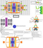
its all in the attached diagram.
boggen new tractor idea75.png
 
   / new tractor idea possibly....
  • Thread Starter
#92  
the large gear inside the 360 joint. instead of a grove and key.. drill some holes through gear into the bottom portion of the 360 joint and tap the holes. and use bolts to hold gear to bottom section. that might hold up a lot better. and transfer forces better.. hhmmsss....

just realized forgot to show bolts that are torqued down to hold top and middle sections together...

thinking there may want to be some sort of "large" reduction gearing. and perhaps some how build a hyd gear pump (done in opposite way, hyd oil spins shaft, vs shaft pumping oil) directly into the reduction gearing and drive gear. then again... it might be better to place motor out side the 360 joint itself.

if motor is placed outside the 360 joint. there really would not be any room above or around the top of the 360 joint. but possibly more room under it... hhmmsss...

been thinking of redoing the "weight distribution" cylinder setup so there are 2 cylinders. making room in center off to a side, for a possible motor to turn the 360 joint.. hmmssss
 
   / new tractor idea possibly....
  • Thread Starter
#93  
is there really need for wires going down to the hydrostatic transmission? what about just sending extra pipes over pipes over pipes... through center of the 360 joint. so only thing that goes back and forth is hyd oil down to the wheels. and then place valving up above the 360 joints. BAH. that would create a bunch of extra junk that would be prone to breaking down.

what about using pipes like "linkages" that went through center of the 360 joint... kinda like linkages / rods that go between levers on tractor to some valve located some place else on the tractor, or down to transmission.

hhmmsss... on other hand, there is going to be a large amount of drive shafts possibly all spinning at different speeds. i would imagine some sort of RPM sensor and torque sensor or like would be wanted. so computer had ability to control traction and adjust speeds.

instead of running multi wires down below the 360 joint. perhaps run a hot, ground, and couple sensor wires. and then put a relay/fuse and computer chip below the 360 joint. computer chip mainly to accept all singles from sensors and then put that info out to the couple sensor wires that come down below the 360 joint.

even if electric motor/s ran the wheels vs hydrostatic transmission/s, i would assume above would still hold true. except instead of hyd oil pipes. there would be room for the larger electrical wires. just to keep amount of wires down to a min amount. and keep the "special" electrical fitting (that rotates with 360 joint) from getting extremely expensive and more prone to failure.
 
   / new tractor idea possibly....
  • Thread Starter
#94  
the 360 joint... hhmmsss "slew" never knew... or even thought of it like a bearing...
supply slewing bearing VLU 200414

lots of bearing types...
Single row ball four-point contact type, Slewing Ring Bearing - China Single row ball four-point contact type Manufacturer & Supplier

bearings hhmmss...
Bearing for sale*|*Archive*|*Slewing bearings

guess it helps to search... saw a couple designs and instead of ball bearings. perhaps rollers, and them some angle rollers or something... for the 360 joint... *rubs chin* so many choices.... time to move onto something else.

=================
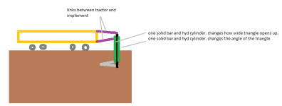
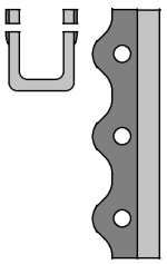
the support frame work for the links around the STB tractor. thinking of some sort of or U channel metal. with extra support err width on the tops of the U were holes would be drilled for PINS. that would hold hyd cylinders, to solid bars. to fold/unfold implements. with holes spaced every 2 to 3 inches for pins... to allow for adjustments and different attach points. for various implements.

boggen new tractor idea76.png
 
   / new tractor idea possibly....
  • Thread Starter
#95  
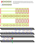
trying out discs configurations....

boggen new tractor idea77.png

at moment like 8 gang (4 on back row, 4 on front row), or 2 gang (1 back row 1 front row). but something is still not there for the 2 gang.

not really happy about the 4 gang (2 back, 2 front). just not seeing it, perhaps it is just physically how and were i placed the blue lines (discs) and not seeing things line up. like i do on the 8 gang.

*shrugs*
 
   / new tractor idea possibly....
  • Thread Starter
#96  
had to draw it

boggen new tractor idea78.png

got so far along. and started to see what a pain in the rear it would be, and a good amount of "failure" points. just one pin/axle goes. and entire tractor could be down. just way to much force would get applied if just one attachment point took all the force from say hitting a rock, and wipe out an entire track. and bending and twisting all the scissor like links...

ah well had to see what it would look it....
 
   / new tractor idea possibly....
  • Thread Starter
#97  
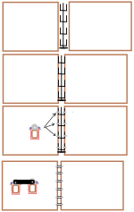
with multi implements being attached to a single side of the STB (side train box) tractor. trying to think of a way to connect the implements together.....

boggen new tractor idea79.png

the 3 prong pitch fork, type of lock you might see on gate or garage door... i was more along thinking might be overall easier. due to it would allow individual implements to slide towards tractor or away from tractor. so one implement might go down or up a hill. while letting the implement right next to it. to still follow the hill some. but still allow some slack to move freely to some extent.

not really liking the pure flat bars. that go between 2 implements. i could almost see them getting twisted and bent. resulting in implements not being able to move as freely. and causing implements wanting to jamb up.

though pending on type of implement or just all together... is there a need to get implements to attach to each other.... it is not like there are already 3pt hitch like hyd links that each implement would connect to.... would it be better to be able to "fold" or raise each implement individually. so if ya getting near to being done and on final pass. being able to raise or fold a couple implements so ya not going back over what you already done....

then again, perhaps instead of the flat bars. putting in some heavy duty springs? hhhmmss...

ya, and i thought looking at all the implements over the years, and then resent googling to look at stuff would make things simple as night and day... time to get back to the basics and reduce complexity....
 
   / new tractor idea possibly....
  • Thread Starter
#98  
bottom plows.... in furrow.... or multi not in furrow setups... hmmss....
boggen new tractor idea80.png
 
   / new tractor idea possibly....
  • Thread Starter
#99  
no longer remember what this implement is called....

boggen new tractor idea81.png

it is not a ripper / potatoes plow. due to the large triangle that is down in the dirt is wide as in 2 to 5 feet width. it almost looked like a tail of an air plane. with the horizontal wings and then the single vertical flap.

if memory serve it, was placed on some sort of tract dozer. just to get the HP, weight, and traction. to pull this thing through the ground.

just assuming. it acted kinda like a bottom plow. but rather it just lifted all the soil above the triangle up. and caused the soil to loosen up and then dropped the soil right back down. without turning the dirt over like a bottom plow. errr acted like a chisel plow or ripper and breaking up the hardpan....

i want to say i remember seeing 2 or 3 triangles on some of these. perhaps the upper triangle was used to keep the implement from going to far down into the soil.
 
   / new tractor idea possibly....
  • Thread Starter
#100  
RECAP 3

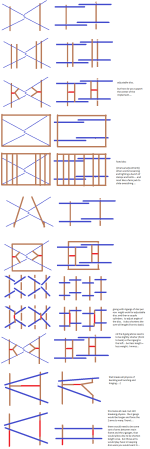
boggen new tractor idea82.png

post# 81 = all diagrams from the previous 80 posts.

been jumping all around on different ideas/subjects.

for most part shortened overall width of machine, and redid how the links (3pt hitch like links) connect to the STB (side train box) tractor.
i suppose i should start saying 2point quick hitch connections.

the quick hitch locking mechanism and implement ends for quick hitch. are still up in the air. of exactly what they may look like. and more of a concept thought. and no actual design to them as of yet.

went through 360 joint. but not really drawn out fully and attempted to fit into the small space for the motor that spins the 360 joint. see posts 90 to 94 for more info on 360 joint. more specifically the special fitting to get between rotating wires... not real sure about the actually how the 360 joint will go together. i kinda went into it, and then left it as is... without redrawing and rechecking..., re thinking about it.

redid cylinder to cylinders for moving wheels back and forth under the machine. though not much detail on them yet.

started to get into various implements but early doings on them... and more currently mind set of looking at various implements and ways that might work for various implements but more chicken scratch drawings. to get a broad over view of how things might work and attach.

still undecided / unsure what would be the primary source for this machine, drive shafts and gearing, electricity, or hyd oil. just really not there yet....

===============
i want to go take another looking at the wheels and the "dead man circle" and look at "tracks" and perhaps transport wheel combination. and possibly loosing the 360 joint and redistributing weight cylinders. that i doubt loosing them will happen. also want to look at a 2 long tracks, and then 2 shorter tracks, (1 long, 1 short) per side of transmission/motors

or going with 4 or 8 short tracts were tracts act like caster wheels, and loosing the primary 360 joint and redistributing weight cylinders (possibility).

along with possible some sort of "suspension" or rather something that might allow the wheels or tracks in this case to slightly lean side to side backwards and forwards just a couple inches. just enough so as to keep all tires or tracks firmly on the ground across the entire width of the tire or track.

at moment kinda thinking if i went with tracks for (field mode) and then a tire on each side for (transport mode). i might be able to reduce the dead man circle. by another couple inches or a couple feet perhaps...
 
 
Top