JustGary
Silver Member
All -
With all of this talk lately of grapples (and just getting 40 acres clear cut), I'm interested in one too. I'd like to just buy one, but I don't have (or want) a QA plate, and it seems that most of the available ones don't use pins.
After talking with Melissa at Markham Welding, I'm strongly considering getting them to cut and weld my design. I'm not opposed to doing it myself, but I'd rather save the time (and get much better welding).
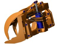
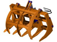
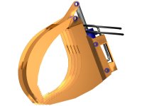
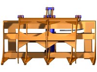
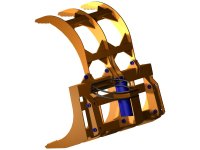
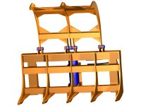
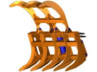
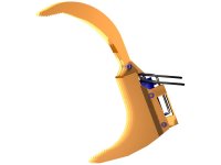
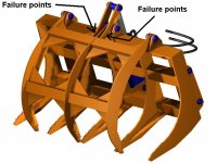
Anyway, one of the photos posted by a TBNer got me thinking about what I want, so I dusted off the ol' CAD program. Please feel free to comment on the design. Keep in mind that it is a 48" grapple for a 28 HP Kubota with the LA463 loader. Some key points:
- 48 3/4" wide
- 3/8" plate construction except for tubing
- Rake uses 3" square tube, 1/4" wall
- Grapple uses 2 1/2" square tube, 1/4" wall
- 1" pins throughout
- 8" stroke DA cylinder from Surplus Center
- Cylinder mounted behind rake for more protection, a distinct advantage over QA plate
- 100 degree jaw movement, opens to 46+" at tips
- Weight not calculated yet (I'm working on that next)
Questions for you to answer (I know I'm asking for it now...):
- Is it strong enough? I suspect yes, but you be the judge.
- Is it too strong? The loader is rated at about 1000 pounds lift, but curl (and ramming) forces are probably much greater.
- Should the grapple overlap the rake when closed (and loose opening distance)?
- What have I missed? Cupholders?
Regards,
- Just Gary
With all of this talk lately of grapples (and just getting 40 acres clear cut), I'm interested in one too. I'd like to just buy one, but I don't have (or want) a QA plate, and it seems that most of the available ones don't use pins.
After talking with Melissa at Markham Welding, I'm strongly considering getting them to cut and weld my design. I'm not opposed to doing it myself, but I'd rather save the time (and get much better welding).
Anyway, one of the photos posted by a TBNer got me thinking about what I want, so I dusted off the ol' CAD program. Please feel free to comment on the design. Keep in mind that it is a 48" grapple for a 28 HP Kubota with the LA463 loader. Some key points:
- 48 3/4" wide
- 3/8" plate construction except for tubing
- Rake uses 3" square tube, 1/4" wall
- Grapple uses 2 1/2" square tube, 1/4" wall
- 1" pins throughout
- 8" stroke DA cylinder from Surplus Center
- Cylinder mounted behind rake for more protection, a distinct advantage over QA plate
- 100 degree jaw movement, opens to 46+" at tips
- Weight not calculated yet (I'm working on that next)
Questions for you to answer (I know I'm asking for it now...):
- Is it strong enough? I suspect yes, but you be the judge.
- Is it too strong? The loader is rated at about 1000 pounds lift, but curl (and ramming) forces are probably much greater.
- Should the grapple overlap the rake when closed (and loose opening distance)?
- What have I missed? Cupholders?
Regards,
- Just Gary
Attachments
-
 Root_Grapple_1a.jpg70.2 KB · Views: 605
 -
 Root_Grapple_1b.jpg78.8 KB · Views: 457
 -
 Root_Grapple_1c.jpg51.6 KB · Views: 403
 -
 Root_Grapple_1d.jpg69.4 KB · Views: 342
 -
 Root_Grapple_1h.jpg56.1 KB · Views: 376
 -
 Root_Grapple_1g.jpg66.8 KB · Views: 401
 -
 Root_Grapple_1f.jpg72 KB · Views: 388
 -
 Root_Grapple_1e.jpg31.5 KB · Views: 383
")