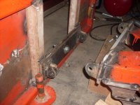
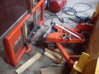
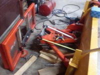
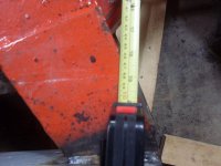
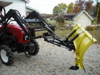
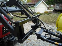
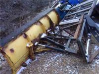
Here's the scoop. I had the plow welded solid to the adapter plate but my some of my welds failed (what else is new) and some of them actually pulled chucks out of the 4" X 1.5" channel they were welded to. So, I decided to make a vertical pivoting setup which is probably what I should have done in the beginning but I was rushing at the time as it was snowing and that was the quickest way to get going. The constant pounding proved to much and metal fatigue set in along with the crude welding. I don't have a picture of the old setup but I had a 3" X 20" stoke cylinder to angle it and that was not the ideal setup either but it work for two winters. I never had the original cylinders from the plow so I don't have them to try and experiment with placement. I kept the vertical pivot point approximately in line with the FEL arms so that the constant pressure is directly applied to them. If I went higher or lower I thought that would put undue stress on the curl cylinders. I cut the infastructure back quite aways back so I don't have a lot of room for cylinder placement, hence I was looking for ideas (pics) to maybe turn the lightbulb on as to what I could do. The pic with the tape measure is blurry but it is to show where the tape is located and then a closeup showing that distance (which is about 22") which is quite a bit shorter than it originally was (probably 30"+). Seeing how the vertical pivot point is far enough off the bottom of the QA, I can't get the cylinders below the QA. I think my problem lies mostly in the fact that I don't have enough room left to place a cylinder on each side of the horizontal pivot point as is normally done. I don't have crossover relief either and I will probably have to get one if I can make two cylinders work on either side. I didn't bother with the relief with the 3" cylinder as it would take a lot more force to pop than a standard 1.5" or 2" cylinder in the same placement as I had before. I geared up a broom handle and a metal rod to simulate a cylinder of a normal plow (17" retracted and a 10" stroke) to help with placement but I always end up too close to the center pivot of the plow (within 3" - 5" inches off center) which I think will create too much force on the cylinders constantly. So I'm reaching out, I know I'm a man and I'm not suppose to give in, but here I am.
Ignore the pivot between the two plates on the QA as that is just for letting the plow follow the lateral contours of the ground. I don't have the stops or enclosure around that done yet but will post pics when I'm done. I geared that up so the outer tips of the plow can travel about 4" to 5" inches up or down.
Steve
P.S.
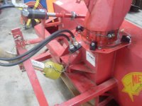
Ignore the snowblower pic, I don't know how I got that on there. That was just a pic after I put the hydraulic motor on for chute rotation.