kyfeworks
New member
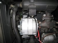
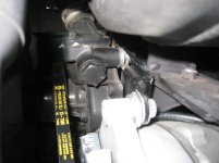
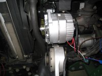
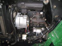
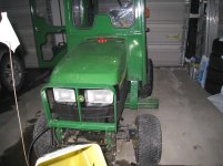
O.K. so I've searched and searched and can't find anything that will directly replace that punky little 20Amp alternator on my 2210. Here is my own upgrade from the original unit to a very common DELCO 10si 70Amp three pin alternator.
*******Disconnect the battery before doing anything**********
1) first things first, toss the JD 20Amp into your project box for future abuse.
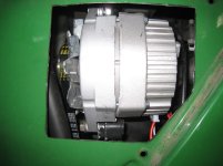
2) acquire a standard DELCO 10si alternator (I bought mine at a rebuild shop for $120CDN and he gave me the two pin connector to go with it).
3) lose the original fan belt and replace it with a GATES 7385 or 7390 (the 7390 is easier to change if you have to but the 7385 lets the new alternator sit closer to the engine).
Now for the real work.
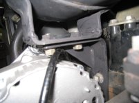
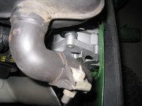
1) You are going to have to shorten the "U" bracket on the bottom of the muffler by almost a half inch. I cut it with my grinder and then welded it back together. A little muffler paint and Bob's your uncle.
2) Now you have to grind down the 45 degree gusset in the "L" bracket that the muffler bracket attaches too and readjust its height to the top of its travel. This allows room for the new Alternator to move for adjustment without touching the motor or muffler. It also will allow space for the Tachometer cable to pass without hindrance.
3) Now you go back to the DELCO and, using a hacksaw or grinder, trim down the LARGE mounting flange so as to make it the same thickness as the thinner mounting flange.
4) Loosen the pulley, 15/16 wrench and an Allen key. Then remove the four screws holding the two halves of the Alternator together. With the pulley side facing up, rotate the top half of the case so as to align the two pin connector of the bottom case to the right of the newly cut-down mounting flange.
5) replace the four screws and re-tighten the front pulley. The alternator is now configured for the correct orientation of the connectors so nothing gets burnt or shorted.
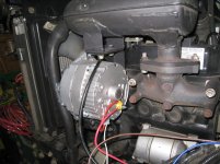
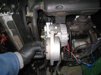
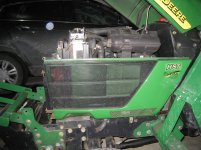
6) mount the new alternator in the old position with the modified flange on the bottom and the connector now facing towards you and down (use the original lower metric bolt and replace the upper metric bolt with a 5/16 x 1" national course thread. you will need to add two 5/16 washers between the alternator and the top mounting bracket and between the thermostat mounting hole and the adjustment arm. I had to do this to make the adjustment arm move freely).
7) install the new Gates Belt and adjust and tighten the alternator.
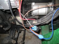
8) connect the #2 pin of the alternator, the sense, directly to the B+ alternator output post and connect this to the Batter B+ post.
9) connect the #1 pin of the alternator, the ignition lead, to one side of the coil circuit of a standard automotive relay (Digikey # PB679-ND). This is going to allow our Charge light in the dash to function normally as well as activate the internal regulator of the 10si.
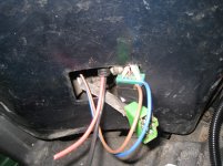
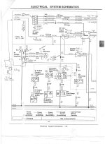
10) open the center cowl cover of the tractor (the one under the instrument panel) and locate and disconnect the original voltage regulator (N1 in the JD schematic), left side near the floor ( a word of warning hear, this is a cramped and uncomfortable place for the regulator so if you're a Christian soul you may want someone else who curses on a regular basis to do this part for you).
11) connect the other end of the coil circuit of the relay to the wiring harness side connector (X17 in the JD schematic) of the old regulator, Red/Blue wire (use a standard blade connector and push it into the contact).
At this point if you reconnect the battery and turn the key to the on position you should hear the relay click. This is a good thing. If you don't hear the click then you've missed something.
disconnect the battery and continue.
12) now run a wire from the pin next to the one you just connected (White/Red wire on X17 connector) back to the relay to the normally open contact.
13) place a jumper between the Ignition side of the relay coil (the one coming from the Red/Blue of X17) to the common contact of the relay.
14 reconnect the battery and turn the ignition key to the on position and verify that you not only hear the relay "click" but you now have an illuminated battery light. If you start the engine the light should go out and the battery voltage should rise to over +14 vdc.
15) disconnect the battery and protect the wires and relay and tidy up the wiring harness.
At this point you have a functioning upgrade but it's a little ugly.
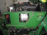
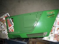
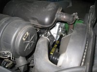
You will now have to modify the left side cowling of the engine compartment to allow for the larger size alternator to fit and not rub anywhere.
16) Hold the cowling up to the correct position (or just hag it from the top pins and leave the bottom pin out) and mark out the area that would be occupied by the new alternator.
17) remove the cowling and remove the protective black screening from the outside.
18) using a grinder with a cutoff disk, cut out the area you just marked and place the cowl back on to test the cut out. Adjust this size until you are happy with the clearances.
At this point you could just re-assemble the black screening onto the cowl and reinstall the cowl and be done. If you do a lot of snow blowing, like I do, then you may want to seal off the weather from the new alternator.
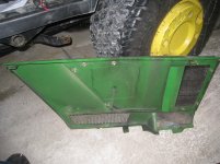
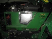
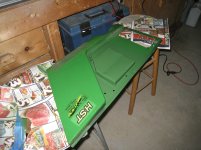
19) make yourself a little "drop in box" for the hole and weld it from the inside of the cowl.
20) Paint and reinstall everything.
I've attached some pictures of my conversion to help clarify the textual description.
Happy building!!
*******Disconnect the battery before doing anything**********
1) first things first, toss the JD 20Amp into your project box for future abuse.
2) acquire a standard DELCO 10si alternator (I bought mine at a rebuild shop for $120CDN and he gave me the two pin connector to go with it).
3) lose the original fan belt and replace it with a GATES 7385 or 7390 (the 7390 is easier to change if you have to but the 7385 lets the new alternator sit closer to the engine).
Now for the real work.
1) You are going to have to shorten the "U" bracket on the bottom of the muffler by almost a half inch. I cut it with my grinder and then welded it back together. A little muffler paint and Bob's your uncle.
2) Now you have to grind down the 45 degree gusset in the "L" bracket that the muffler bracket attaches too and readjust its height to the top of its travel. This allows room for the new Alternator to move for adjustment without touching the motor or muffler. It also will allow space for the Tachometer cable to pass without hindrance.
3) Now you go back to the DELCO and, using a hacksaw or grinder, trim down the LARGE mounting flange so as to make it the same thickness as the thinner mounting flange.
4) Loosen the pulley, 15/16 wrench and an Allen key. Then remove the four screws holding the two halves of the Alternator together. With the pulley side facing up, rotate the top half of the case so as to align the two pin connector of the bottom case to the right of the newly cut-down mounting flange.
5) replace the four screws and re-tighten the front pulley. The alternator is now configured for the correct orientation of the connectors so nothing gets burnt or shorted.
6) mount the new alternator in the old position with the modified flange on the bottom and the connector now facing towards you and down (use the original lower metric bolt and replace the upper metric bolt with a 5/16 x 1" national course thread. you will need to add two 5/16 washers between the alternator and the top mounting bracket and between the thermostat mounting hole and the adjustment arm. I had to do this to make the adjustment arm move freely).
7) install the new Gates Belt and adjust and tighten the alternator.
8) connect the #2 pin of the alternator, the sense, directly to the B+ alternator output post and connect this to the Batter B+ post.
9) connect the #1 pin of the alternator, the ignition lead, to one side of the coil circuit of a standard automotive relay (Digikey # PB679-ND). This is going to allow our Charge light in the dash to function normally as well as activate the internal regulator of the 10si.
10) open the center cowl cover of the tractor (the one under the instrument panel) and locate and disconnect the original voltage regulator (N1 in the JD schematic), left side near the floor ( a word of warning hear, this is a cramped and uncomfortable place for the regulator so if you're a Christian soul you may want someone else who curses on a regular basis to do this part for you).
11) connect the other end of the coil circuit of the relay to the wiring harness side connector (X17 in the JD schematic) of the old regulator, Red/Blue wire (use a standard blade connector and push it into the contact).
At this point if you reconnect the battery and turn the key to the on position you should hear the relay click. This is a good thing. If you don't hear the click then you've missed something.
disconnect the battery and continue.
12) now run a wire from the pin next to the one you just connected (White/Red wire on X17 connector) back to the relay to the normally open contact.
13) place a jumper between the Ignition side of the relay coil (the one coming from the Red/Blue of X17) to the common contact of the relay.
14 reconnect the battery and turn the ignition key to the on position and verify that you not only hear the relay "click" but you now have an illuminated battery light. If you start the engine the light should go out and the battery voltage should rise to over +14 vdc.
15) disconnect the battery and protect the wires and relay and tidy up the wiring harness.
At this point you have a functioning upgrade but it's a little ugly.
You will now have to modify the left side cowling of the engine compartment to allow for the larger size alternator to fit and not rub anywhere.
16) Hold the cowling up to the correct position (or just hag it from the top pins and leave the bottom pin out) and mark out the area that would be occupied by the new alternator.
17) remove the cowling and remove the protective black screening from the outside.
18) using a grinder with a cutoff disk, cut out the area you just marked and place the cowl back on to test the cut out. Adjust this size until you are happy with the clearances.
At this point you could just re-assemble the black screening onto the cowl and reinstall the cowl and be done. If you do a lot of snow blowing, like I do, then you may want to seal off the weather from the new alternator.
19) make yourself a little "drop in box" for the hole and weld it from the inside of the cowl.
20) Paint and reinstall everything.
I've attached some pictures of my conversion to help clarify the textual description.
Happy building!!
Attachments
-
 IMG_9357.jpg556.8 KB · Views: 238
 -
 IMG_9358.jpg658.9 KB · Views: 413
 -
 IMG_9359.jpg621.4 KB · Views: 277
 -
 IMG_9360.jpg654.5 KB · Views: 770
 -
 IMG_9361.jpg394.6 KB · Views: 140
 -
 IMG_9362.jpg556.4 KB · Views: 211
 -
 IMG_9363.jpg597.5 KB · Views: 156
 -
 IMG_9364.jpg375.2 KB · Views: 177
 -
 IMG_9365.jpg612.1 KB · Views: 143
 -
 IMG_9373.jpg759.8 KB · Views: 119
 -
 IMG_9374.jpg530.2 KB · Views: 147
 -
 IMG_9375.jpg574.6 KB · Views: 232
 -
 IMG_9376.jpg451.5 KB · Views: 128
 -
 IMG_9377.jpg544.5 KB · Views: 160
 -
 IMG_9378.jpg630.7 KB · Views: 128
 -
 IMG_9379.jpg827.8 KB · Views: 142
 -
 IMG_9380.jpg654.9 KB · Views: 165
 -
 IMG_9381.jpg461.5 KB · Views: 151
 -
 IMG_9382.jpg553.9 KB · Views: 134
 -
 IMG_9383.jpg486.2 KB · Views: 146
 -
 JD2210 electrical charging circuit mods.jpg802.2 KB · Views: 1,247
