Installation Instructions for 12VDO3S Valve Kit for the Massey Fergus1635, DL120 w/Valve under Tractor. No Cab
Agco Diverter Plug Part Number SL103119 and O-Ring Part Number SL103143 need to be purchased from an agco dealer.
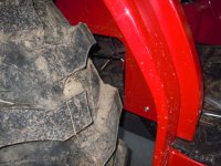
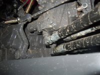
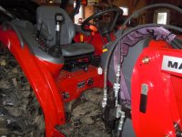
1. Locate the loader post that is bolted to the right side of the tractor. It is painted black. There is a bolt that holds the strap that is used to hold the 4 work hoses. Using this bolt mount the bucket valve bracket so that the tab rest on the back edge of the loader mounting bracket. See photo #1
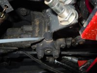
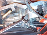
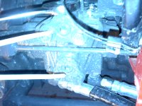
2. The loader valve is located just in front the right rear wheel axel. It is behind a sheet metal panel on the wheel well fender. Remove the four bolts that secure this cover to access the valve. See photo # 2 and 3
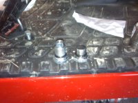
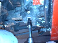
3. Remove the plug on top of the valve and install the (Dealer Provided) diverter plug and o-ring. See photo # 4, 5, and 6. (the longer plug on the left in picture 6 is the Agco dealer diverter plug, and the one on the right is the stock plug that has been removed)
4. There are two allen head set screws located vertical to each other just below the diverter plug. Remove these two set screws. See photo #7 and 8
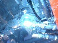
5. There are two 90 degree adaptors provided in the kit to replace the two set screws that were removed in item 4. Install the adaptor with out the nut in the top port (pipe tape is required). Install the adaptor with the nut on the bottom port. This is a tight fit. You may need to connect the hoses in item 6 and 7 to determine the best rotation for the 90 fitting. Both will need to be pointing toward the front of the tractor and down up to 30 degrees. See photo #9
6. Using one of the ス hoses, attach one end to the adaptor that was just installed to the top port on the loader valve and connect the other end to the 撤 port of the W. R. Long valve.
7. Using the other ス hose attach one end to the adaptor that was just installed to the bottom port of the loader valve and connect the other end to the 典 port on the W. R. Long valve.
8. Install remaining 2 hoses to the W. R. Long valve and the other ends to the back of the bucket.
9. Slide the hand grip and rocker switch assembly down over the joy stick, with care not to damage the wires and secure it with the two set screws. Connect the red wire from the rocker switch to a hot wire on the tractor using the 10 amp in line fuse. Connect one of the black wires from the joy stick to one of the black wires on the W. R. Long valve. Connect the other black wire from the joy stick to the other black wire on the W. R. Long valve.
Agco Diverter Plug Part Number SL103119 and O-Ring Part Number SL103143 need to be purchased from an agco dealer.
1. Locate the loader post that is bolted to the right side of the tractor. It is painted black. There is a bolt that holds the strap that is used to hold the 4 work hoses. Using this bolt mount the bucket valve bracket so that the tab rest on the back edge of the loader mounting bracket. See photo #1
2. The loader valve is located just in front the right rear wheel axel. It is behind a sheet metal panel on the wheel well fender. Remove the four bolts that secure this cover to access the valve. See photo # 2 and 3
3. Remove the plug on top of the valve and install the (Dealer Provided) diverter plug and o-ring. See photo # 4, 5, and 6. (the longer plug on the left in picture 6 is the Agco dealer diverter plug, and the one on the right is the stock plug that has been removed)
4. There are two allen head set screws located vertical to each other just below the diverter plug. Remove these two set screws. See photo #7 and 8
5. There are two 90 degree adaptors provided in the kit to replace the two set screws that were removed in item 4. Install the adaptor with out the nut in the top port (pipe tape is required). Install the adaptor with the nut on the bottom port. This is a tight fit. You may need to connect the hoses in item 6 and 7 to determine the best rotation for the 90 fitting. Both will need to be pointing toward the front of the tractor and down up to 30 degrees. See photo #9
6. Using one of the ス hoses, attach one end to the adaptor that was just installed to the top port on the loader valve and connect the other end to the 撤 port of the W. R. Long valve.
7. Using the other ス hose attach one end to the adaptor that was just installed to the bottom port of the loader valve and connect the other end to the 典 port on the W. R. Long valve.
8. Install remaining 2 hoses to the W. R. Long valve and the other ends to the back of the bucket.
9. Slide the hand grip and rocker switch assembly down over the joy stick, with care not to damage the wires and secure it with the two set screws. Connect the red wire from the rocker switch to a hot wire on the tractor using the 10 amp in line fuse. Connect one of the black wires from the joy stick to one of the black wires on the W. R. Long valve. Connect the other black wire from the joy stick to the other black wire on the W. R. Long valve.
Attachments
-
 1.JPG225.1 KB · Views: 450
 -
 2.JPG218.8 KB · Views: 298
 -
 4.JPG224.7 KB · Views: 350
 -
 5.jpg339.1 KB · Views: 363
 -
 6.jpg248.9 KB · Views: 353
 -
 7.jpg301.5 KB · Views: 317
 -
 8.jpg251.6 KB · Views: 327
 -
 9.jpg283.8 KB · Views: 325
 -
 10.JPG226 KB · Views: 397
 -
 11.JPG193.6 KB · Views: 375
 -
 12.JPG222 KB · Views: 437