lennyzx11
Veteran Member
- Joined
- Dec 20, 2015
- Messages
- 1,255
- Location
- Bennington Vermont
- Tractor
- Kubota L3301 HST/LA525 & 1964 Ford 2000 gas
I had a little time today between three year olds naps and rain to get the 2n pump dropped out. I had removed the lift cylinder prior and only had to remove the top cover this time.
Short version.
Removed all three drain plugs working from back to front of the rear axle,hyd pump, & transmission. About 5 gallons come out so be ready with that much capacity in drain pans.
Removed top cover. (Again)
Removed 4 bolts holding PTO shaft housing on rear of axle and used a chisel to gently tap it apart at bottom and top the used screw driver to work it loose. Removed pto shaft.
Removed all bottom bolts holding pump in place. Then pried/chiseled (GENTLY !) around base gasket to break pump loose from main housing. Once loose. Pump has to be slid back in order to clear front in order to drop down. Then it'll fall out so be ready with a catcher or a jack. Mine landed on the piece of old foam rubber I had under it happily.
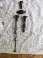
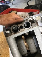
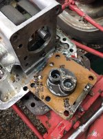
Then after wiping most of the oil off, I took it apart. There are springs, valves, and rods, hidden inside various passages that don't fall out easily but can come out as you are cleaning so make sure you get everything out. I had to use hemostats in a couple of places to get everything out.
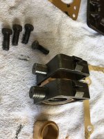
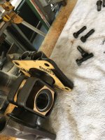
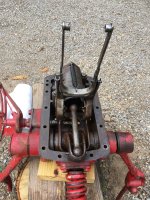
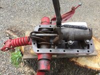
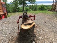
Looking from front of tractor, here's mine just out.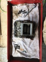
Notice the longer 4 bolts on one side for the valve blocks? There's a difference.
I must have not got the break down picture that thought I had so will take it tomorrow all laid out.
Tore everything apart, three year old granddaughter woke from nap and we went to town for diesel and ice cream. When returned home, all is soaking overnight in diesel.
Granddaughter soaking in tub with chocolate ice cream residue while soaking grandmother splashing while grandpa is hiding out in shop!
Though I ordered a "complete" kit, and a control valve, it appears I didn't get a pressure relief/safety valve. So I think I'll order it now. Not sure of a way to test the old one with layman's tools.
Found two valve springs broke and control valve assembly has a chunk out of it so far.
I think that was from previous owner removing lift cover without disconnecting control rods to valve though. I found it loose inside and hanging originally.
Short version.
Removed all three drain plugs working from back to front of the rear axle,hyd pump, & transmission. About 5 gallons come out so be ready with that much capacity in drain pans.
Removed top cover. (Again)
Removed 4 bolts holding PTO shaft housing on rear of axle and used a chisel to gently tap it apart at bottom and top the used screw driver to work it loose. Removed pto shaft.
Removed all bottom bolts holding pump in place. Then pried/chiseled (GENTLY !) around base gasket to break pump loose from main housing. Once loose. Pump has to be slid back in order to clear front in order to drop down. Then it'll fall out so be ready with a catcher or a jack. Mine landed on the piece of old foam rubber I had under it happily.
Then after wiping most of the oil off, I took it apart. There are springs, valves, and rods, hidden inside various passages that don't fall out easily but can come out as you are cleaning so make sure you get everything out. I had to use hemostats in a couple of places to get everything out.
Looking from front of tractor, here's mine just out.

Notice the longer 4 bolts on one side for the valve blocks? There's a difference.
I must have not got the break down picture that thought I had so will take it tomorrow all laid out.
Tore everything apart, three year old granddaughter woke from nap and we went to town for diesel and ice cream. When returned home, all is soaking overnight in diesel.
Granddaughter soaking in tub with chocolate ice cream residue while soaking grandmother splashing while grandpa is hiding out in shop!
Though I ordered a "complete" kit, and a control valve, it appears I didn't get a pressure relief/safety valve. So I think I'll order it now. Not sure of a way to test the old one with layman's tools.
Found two valve springs broke and control valve assembly has a chunk out of it so far.
I think that was from previous owner removing lift cover without disconnecting control rods to valve though. I found it loose inside and hanging originally.
