Adding Spool Valves

   / Adding Spool Valves #1  

niemeyjt

Silver Member
Joined
Jun 4, 2009
Messages
246
Location
Suffolk UK / Lausanne CH
Tractor
Kubota B1750
I want to add a couple of rear double acting spool valves to my Kubota B1750 with KBF200 Loader.

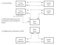
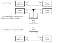
Currently, I have the detatchable loader plumbed into the hydraulics, so I will fit it in there in series. When loader is detatched, I there is a loop of pipe that connects hydraulic pipe output and input which needs to be retained in some form obviously. My question is over the order of connection - should the flow be

1. pump -> loader -> rear valves -> pump

or

2. pump -> rear valves -> loader -> pump

or

3. does not matter (in which case I will do what is neatest, probably 2)

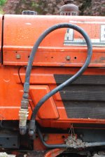
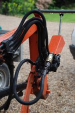
As I say, the loader has only two pipes to the tractor - feed and return.

TIA

J
 
   / Adding Spool Valves #2  
J:

I just went through this whole thing myself. You have already answered one of the typical questions, your machine has an open center hyd. system. Either the new double acting valves for the rear remotes or the FEL valve must have a "power beyond" port. The high pressure side of the system must be operated in series and a return to the pump must always be provided. The return ports only return the displaced oil from the cylinders and do not provide enough flow for powering other hyd. beyond the valve, hence "power beyond." The process I went through was trying to think through how indepenent I wanted the front and rear hyd. circuits to be. I decided I wanted the ability for them to be completely independent. Depending on where the pump output goes first this may make a differnce in your situation in terms of plumbing the whole thing together. It did on mine which is a Kubota L4310.

You might check your existing loader valve to see if it has a power beyond port. They are usually labeled "PB." If it does and you tap into it your FEL valve will have three lines, the high pressure line (existing), the power beyong high pressure line (new) and the low pressure, or return line (existing).

I hope this helps at least a little.
 
   / Adding Spool Valves
  • Thread Starter
#3  
Thanks

There is nothing visibly labeled PB - just in and out on the loader valve block. The loader valve block remains on the loader when detatched.

I have taken a couple of pictures - the loader is off today for mowing if the rain stops!.

On the tractor and the loader there are two new (shiney) female quick fits on the 'out' side of things. In the photos, the 'in' pipe and 'out' port are looped together on both the tractor and the loader.

When loader is fitted, the pipes currently looped into the female 'out' ports are swapped over - so the pipe on the loader connects to the female port on the tractor and vice versa.

I had assumed that the 'out' pressure from the loader was still high and that it was not some form of low pressure return. This would suggest I need to go for option 2 and get the rear valve block with PB to go on to supply the loader and find way to connect the third (low pressure return) from the rear valve block into the gearbox sump - or could/should it be Tee'd into the existing low pressure return?

J
 

Attachments

  • DSC_0007.jpg
    DSC_0007.jpg
    834.8 KB · Views: 816
  • DSC_0008.jpg
    DSC_0008.jpg
    535.4 KB · Views: 769
   / Adding Spool Valves #4  
You have the general idea. The new valve must be plumbed in series. Since you existing valve does not have a PB port (also commonly labeled BYD), you can use the OUT port to feed the new valve. What Cycle described about the OUT port only providing waste ol from the cylinders only applies when there is a PB setup.

To keep things simple, you can use a new valve that is NOT equiped with a PB plug. This is not the ideal way-but it is acceptable. Your option #1 seems the best to me.
 
   / Adding Spool Valves
  • Thread Starter
#5  
I have tried to put the two designs above into a picture - sorry, I am not very good at Powerpoint.

Is it a case that either will work? Will the T in no 2 be an issue?

TIA

J
 

Attachments

  • hydraulics.jpg
    hydraulics.jpg
    48.2 KB · Views: 838
   / Adding Spool Valves #6  
You CANNOT Tee into high pressure lines. ALL valves MUST be added in series. If you Tee into the lines, the fluid will "take the path of least resistance" and you will not get any usable flow at either valve.

So your drawing #2 will nor work. To add a PB valve, you still plumb in series...but the PB (BYD) port goes to the next valve in the chain, and the T (or OUT) port goes to the tank to take care of the waste oil from the work ports.

Clear as mud;)
 
   / Adding Spool Valves
  • Thread Starter
#7  
Thanks for the advice - diagram 2 was based on the premise that output from loader valve was low pressure.

Diagram 4, I think, reflects Kenny's latest advice.

Diagram 3 looks like becoming my favourite.

J
 

Attachments

  • hydraulics2.jpg
    hydraulics2.jpg
    49.3 KB · Views: 739
   / Adding Spool Valves #8  
Thanks for the advice - diagram 2 was based on the premise that output from loader valve was low pressure.

Diagram 4, I think, reflects Kenny's latest advice.

Diagram 3 looks like becoming my favourite.

J

Yes, now you got it;)
 
   / Adding Spool Valves #9  
Some say that you can not tee into a high pressure line. I believe you can, using common knowledge that high pressure is generated when the flow meets a resistance, like a 3ph valve at max, or a cyl fully extended or retracted. If you have a tee in the circuit, and the 3ph is closed, normally the relief would relieve the pressure, say at 2500 psi. Now, let's say that an aux valve has been teed in and operates a cylinder. If you operate the teed in valve and the 3ph at the same time, then the pressure will build up as the cyl is activated to lift a load. If the pressure exceeds the the 2500 , that relief valve will go off until the pressure is relieved. There might be a reason to tee into a high pressure line for simplicity sake. A gate valve in each leg, would simplify this as you would turn the gate valve to shut off one leg of the tee. So, it can be done, but only do it with caution. If you operate one valve at a time, the fluid will go through the path of least resistance, which will be the other valve. You could get by without the gate valves if you use common sense, and that is if the 3ph is up, then the flow will be forced through the aux valve and then you can use that valve to operate whatever.

Off course, any valve upstream will take all or most of the fluid first. Any fluid left over from the upstream valve can be used by the other circuits, no matter how small a flow.

This is only meant to stimulate thought, and not to confuse. Think about it and decide for your self. I know some of you do stuff, that you will not tell anybody else to do. It might work well for you , and not for others that do not fully understand.

If anyone can prove that it will not work, I will delete the post., and apologize for my ignorance.

Correct me if I am wrong, and I know you all will do just that.
 
   / Adding Spool Valves #10  
Some say that you can not tee into a high pressure line. I believe you can, using common knowledge that high pressure is generated when the flow meets a resistance, like a 3ph valve at max, or a cyl fully extended or retracted. If you have a tee in the circuit, and the 3ph is closed, normally the relief would relieve the pressure, say at 2500 psi. Now, let's say that an aux valve has been teed in and operates a cylinder. If you operate the teed in valve and the 3ph at the same time, then the pressure will build up as the cyl is activated to lift a load. If the pressure exceeds the the 2500 , that relief valve will go off until the pressure is relieved. There might be a reason to tee into a high pressure line for simplicity sake. A gate valve in each leg, would simplify this as you would turn the gate valve to shut off one leg of the tee. So, it can be done, but only do it with caution. If you operate one valve at a time, the fluid will go through the path of least resistance, which will be the other valve. You could get by without the gate valves if you use common sense, and that is if the 3ph is up, then the flow will be forced through the aux valve and then you can use that valve to operate whatever.

Off course, any valve upstream will take all or most of the fluid first. Any fluid left over from the upstream valve can be used by the other circuits, no matter how small a flow.

This is only meant to stimulate thought, and not to confuse. Think about it and decide for your self. I know some of you do stuff, that you will not tell anybody else to do. It might work well for you , and not for others that do not fully understand.

If anyone can prove that it will not work, I will delete the post., and apologize for my ignorance.

Correct me if I am wrong, and I know you all will do just that.

You are fine J_J...I see your idea, and it is basically the same thing as how an Open Center, multiple spool, control valve works....

If you tee off from an open center circuit, you add a closed center valve. To build pressure for that closed center valve, you stall cylinder A and keep holding the valve activated......if you do not open up flow to cylinder B , the RV will by pass flow at max pressure, but when the closed center valve open for flow to cylinder B, everything will work just fine.....

An option to stalling the cylinder A, is to have an on/off solenoid valve, to build pressure for cylinder B.....that valve could be controlled by a limit switch on the closed center valve spool neutral position ....neutral and on/off valve is open, when lever on the closed center valve is operated, the on/off valve activates from the limit switch.....:thumbsup:
 

Tractor & Equipment Auctions

2017 Vermeer SC30TX Stump Grinder (A48837)
2017 Vermeer...
2009 GMC T7500 CAB & CHASSIS (A50505)
2009 GMC T7500 CAB...
2001 STERLING WATER TRUCK (A50458)
2001 STERLING...
New/Unused Pallet of 22 Straps (A48837)
New/Unused Pallet...
(1) 8ft Tarter Gate (A48837)
(1) 8ft Tarter...
UNUSED CFG MINI EXCAVATOR ATTACHMENT SET (A50460)
UNUSED CFG MINI...
 
Top