And another set of grapples

   / And another set of grapples #1  

kcprecision

Bronze Member
Joined
Oct 10, 2008
Messages
50
Location
Southern Oregon
Tractor
1973Ford 4000
This past couple /three weeks I have been working on a set of grapples for the bucket on the front end loader. This is the bucket that I purchased a couple of months ago and had to modify to fit the FEL.

These are not as elegant as Loretta's (Mrs 3RRL)but they should work.I did get a lot of inspiration the grapples from her posts.

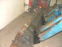
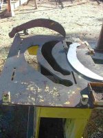
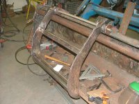
The material that the bucket is made from is not real heavy, about a 1/8 鍍hick so I made a bracket the grapples would bolt to. This bracket is a piece of rectangular tubing 2X4X1/4 inch and reaches across the top of the bucket and is bolted to the sides of the bucket where the material is thicker. There is a flat bar factory welded to the front edge of the side of the bucket and that is what I bolted the rectangular tubing to.

I numbered the pictures so I may do some skipping of the numbers, believe me I can count.
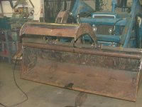
Picture one is the bracket, notice the four holes in the side of the bucket.

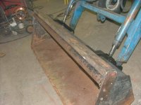
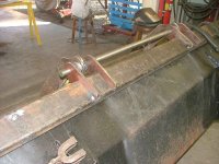
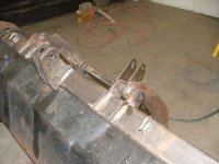
Picture 3 is a better view of the side.

My computer drawing program is Auto Sketch. It does well but is not on a par with a real Cad program but it does work for me. I draw something up on the program and print it out. Than that print gets glued to a piece of masonite and that masonite(spelling) is cut out into the pattern for cutting the metal.
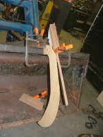
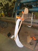
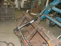
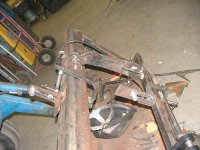
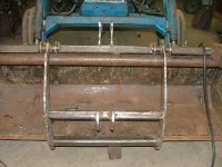
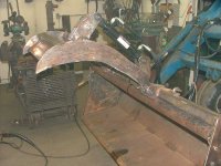
Pictures 4 and 5 are the pattern for the grapple teeth.

In the pictures the patterns are mocked up to check fit and to find the pivots points for the cylinder and for the teeth. I tried using the drawing program to find the pivot points but after some period of time I gave up and went at it this way.

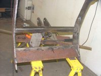
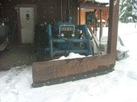
Picture 7 is what I used to cut the teeth from. The big box thing was the guard for the grinding wheel on the stump grinder that I scrapped out and used to make the back blade for the tractor. This is called recycling.

The teeth are at the far end of the box. I have them bolted together and clamped and had been using an angle grinder to get them the same shape. This being ス metal I was using the O/X tourch and I shake too much to get a nice even cut. My plasma would have cut the teeth and I could have used the masonite pattern and cut around it, but it would have used up a cutting tip and the tips are about $14 now and I was down to my last tip.
 

Attachments

  • Number 1.JPG
    Number 1.JPG
    50.1 KB · Views: 302
  • Number 3.JPG
    Number 3.JPG
    53.9 KB · Views: 248
  • Number 4.JPG
    Number 4.JPG
    87.5 KB · Views: 365
  • Number 5.JPG
    Number 5.JPG
    82.8 KB · Views: 316
  • Number 7.jpg
    Number 7.jpg
    55.9 KB · Views: 395
   / And another set of grapples #2  
looking good! be sure to keep us posted with pics.....

this is on my to-do list.......hopefully this winter but with the way things are going, i doubt i make it
 
   / And another set of grapples
  • Thread Starter
#3  
In this set the grapple teeth are ready and it is time to find the pivot point on the 2X4 tube.
Picture 6 and7, the grapples are tack welded together just in case I need to change something when the hydraulic cylinder arrives. The teeth were bolted together and clamped to the mill table the bolt was than removed and the hole was located under the mill spindle and the hole opened up to one inch. A boring head was to bore the hole to fit the sleeve.

The sleeves were than put in the lathe and faced to length. After the facing the sleeves were bolted to the welding table and a tooth was slipped over the sleeve. The tooth location on the sleeve was adjusted using a couple of parallels under the tooth and than the tooth was clamped to the welding table and welded in place..

I ordered a 2X8 stroke cylinder from Surplus Center and would arrive in about 10 days. They had a good price and I have purchased things from them before with good results. When the cylinder arrived I was able to start trying to locate the anchor points for the cylinder.

The long bar is just to keep things in line as I tack welded the teeth anchor points in place. The two spreader bars are 2X2X1/4 tubing 271/2 inches long.

Picture 8 is the lash up that I used to locate the anchor points for the cylinder. I cut some slots in some pieces of angle and bolted them together. That way they were adjustable for angles and the length of the anchor.

I played around putting the cylinder in different positions until I got the greatest amount of opening of the grapple. I was not to get as much opening as I would have liked but will have to live with what I did get.

Most of the problem was that the top of the bucket sloped 26 degrees toward the back of the bucket and I welded the 2X4 tubing at the same angle as the slope. That caused the tubing to interfere with cylinder as the cylinder closed the grapple teeth. I probably should have welded the 2X4 tubing parallel with the floor of the bucket.

Picture 9 is a test run with the cylinder in place. Because the center line of the tooth pivot points were almost in a direct line with the cylinder center line I had to cut and drop the tooth pivot center line below the cylinder center line.


Picture 10 All the pivot and anchor points are located and the anchor plates are cut out and the pin holes have been drilled for one inch pins. The anchor plates are being permanently welded in place with most of the welding completed. The tack welds on the top 2X2 tube had to be cut loose and the tube relocated.
 

Attachments

  • Picture 18.JPG
    Picture 18.JPG
    70.2 KB · Views: 322
  • Picture 9.5.JPG
    Picture 9.5.JPG
    66 KB · Views: 226
  • Number 9.JPG
    Number 9.JPG
    64.4 KB · Views: 201
  • Number 8.JPG
    Number 8.JPG
    69.3 KB · Views: 340
  • Picture 14.JPG
    Picture 14.JPG
    53.2 KB · Views: 235
   / And another set of grapples #4  
Looks pretty good to me and it looks like you're building the grapple out of stout steel so it should hold up well. Keep the pictures coming as you make more progress.
 
   / And another set of grapples #5  
Hi Charlie,
Glad to see you got your grapple project going.
I see you figured out the pivot points after all. One thing I should mention, you found that bar interfered with your cylinder ... so be sure that the cylinder does not interfere with the cross tube between the 2 jaws either. I'm sure you've already checked that, but thought to bring it up.
I see you already got hooks on that long bar too.
The project is looking very good!!
Rob-
 
   / And another set of grapples
  • Thread Starter
#6  
Mike,The tubing is 1/4 inch, the teeth is 1/2 inch. The anchors points are 3/8. The plasma torch will cut quite a bit more 3/8 than 1/2 so that is why the 3/8 was used..

Thanks Rob, I can use all the help I can get. Yes, I did check the lower tube.
 
   / And another set of grapples
  • Thread Starter
#7  
The cylinder anchor points as well as the tooth anchor points are welded in solid. God, I hope that I don稚 have to cut any of them out as they are really welded in.

Picture 15 all of the welding on the frame is completed with only a plate across the two teeth to be added. In the picture the two lower anchor points for the cylinder rod look like they are twisted but they are not. Just a fluke of the camera or maybe it is an operator error.

In picture 16 the plate that was mentioned above is welded across the teeth. I left the lower edge straight as it will help fill the bucket if needed or will rake in a rock or what ever. The bar across the top of the plate is the lower piece of 2X2 tubing shown in the other pictures. I have thought that if needed, I can weld a stiffener between the cylinder rod anchor and the 2x2.

Picture 17, here it is all put together and being tested, for the most part it is working well. There is one problem though. The center line of the teeth pivot points are too close to the center line of the cylinder and when the bucket is tipped backward, I can稚 get enough pressure on the tractor hydraulics to open the grapple. It will work fine if I have the bucket level or just tipped forward.
The tractor hydraulics should be some where around 2500 to 3000 lbs. but as old as the tractor is, it may not generate this pressure. Some day I will put a pressure gage on the hydraulics and see just what the pressure is being produced. The tractor is a 1973 ford.

Pictures 17 and 18 the grapple is wide open, I would have liked the teeth to open more but as I said the angle of the top of the bucket may have been the problem as I never could get the teeth to open any more when I was working on finding the points to anchor the cylinder.

Thanks for looking and for any comments. This was a fun project as most of them are. I hate that I will have to wait until spring to try them out. The snow arrived and I had to put the snow blade on the loader.

Picture 19 is the snow blade that I made last spring. It was completed to late in the year so it did not get tested. There is nothing wrong with your eyes, those spots before your eyes are natureç—´ doing.

Rob, we talked about the tooth bar, I don't think a tooth would be real useful for me. What I might do is weld some 2X2 tubing to a bar, some what like a tooth bar, but the tubing would stick out in front of the bucket about 12 inches or so.
 

Attachments

  • Picture 19.JPG
    Picture 19.JPG
    70.7 KB · Views: 222
  • Picture 21.JPG
    Picture 21.JPG
    53.3 KB · Views: 197
  • Picture 22.JPG
    Picture 22.JPG
    65.3 KB · Views: 247
  • Picture 23.JPG
    Picture 23.JPG
    55.9 KB · Views: 231
  • 2008_1215Image0010.JPG
    2008_1215Image0010.JPG
    52 KB · Views: 237
   / And another set of grapples #8  
KC, goodlooking grapple you've got there.

I know what you're saying in respect to Mrs. 3RRL's work. I just completed my grapple in November. shaking hands makes for lot of grinding. I went thru a lot of patterns before I came up with something I liked.
My only concern is your cylinder attachment point at the tube. When you clamp down on something the force may be great enough to bend the tube.
You might think about putting some gussets in.

I built mine out of a combination of new & old steel. (new round & flat bar stock, the tines were out of some 3/8" I had laying around. plus a cylinder I scrounged up, which ended up being a major problem.) the first cylinder was 3x8, which created enough force to bend the 3/8" attachment plate, as well as the bucket attachment around the reinforcing plates.
Calculating the force created by the cylinder is easy, knowing how much force you actually need or how much force it takes to bend steel is a little out of my expertise. Dropping the cylinder size from 3 to 2 cut the force by a little better than half and made the rework considerably less.:)

I'm sure you can't wait to test it out. (I know I couldn't)
 
   / And another set of grapples #9  
Great job Charlie.
Looks like a little paint and you are done.
Adding those 2 x 2 x 12 "teeth" will be just like a toothbar. That will work hand in hand with the grapple, especially for clearing large mounds of debris like shrubs, sticks and logs and stuff like that.
I would at least grapple a snow man or something for effect.:D
 
   / And another set of grapples
  • Thread Starter
#10  
Firedog, I have had some thoughts on reinforcing the tube some. My thoughts are to add a gusset between the rod anchor point and the second bar. The second bar is welded to the plate so every thing should be strong enough than.

Rob, I hate painting but probably will paint it and the back blade and the loader snow blade and a couple of other things. Heck that will take up the hole next summer.:eek:
 

Tractor & Equipment Auctions

Volvo 9.5 Cu Yd Hydraulic Loader Bucket (A50322)
Volvo 9.5 Cu Yd...
40' CONTAINER (A51244)
Frontier FM2015 (A50120)
Frontier FM2015...
2006 John Deere HPX Gator 4x4 Utility Cart (A50324)
2006 John Deere...
1997 GROVE TMS750B 50' TON CRANE (A52141)
1997 GROVE TMS750B...
Crash Mobile S/A Trailer (A50324)
Crash Mobile S/A...
 
Top