Another Toothbar Solution

   / Another Toothbar Solution #1  

Anonymous Poster

Epic Contributor
Joined
Sep 27, 2005
Messages
29,678
Picture 1
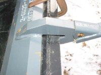
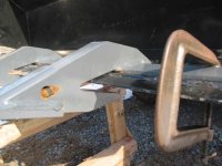
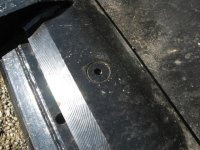
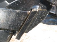
The FEL has a heavy-duty bucket, but it still isn't suitable for aggressive digging. I purchased a heavy-duty toothbar thinking that it was going to be a good solution. The complaints were that it did not fit well against the factory knife edge. As you can see, the fit looks normal from the top.
 

Attachments

  • 246096-Img_0127b.jpg
    246096-Img_0127b.jpg
    34.8 KB · Views: 1,262
   / Another Toothbar Solution
  • Thread Starter
#2  
Picture 2
This picture shows that there is approximately .500 inch gap between the toothbar and the bottom of the factory knife edge.
 

Attachments

  • 246097-Img_0131b.jpg
    246097-Img_0131b.jpg
    41.8 KB · Views: 955
   / Another Toothbar Solution
  • Thread Starter
#3  
Picture 3
This picture shows the back edge of the factory knife edge. The holes shown were factory drilled and were of no use.
 

Attachments

  • 246099-Img_0130b.jpg
    246099-Img_0130b.jpg
    38.5 KB · Views: 769
   / Another Toothbar Solution
  • Thread Starter
#4  
Picture 4
This picture shows a side view of the gap. There are 2 carriage bolts provided by the factory to hold the toothbar in place against the bucket sidewalls. The toothbar mounting brackets are in the inside of the bucket.
 

Attachments

  • 246101-Img_0133b.jpg
    246101-Img_0133b.jpg
    57.6 KB · Views: 641
   / Another Toothbar Solution
  • Thread Starter
#5  
Picture 5
The solution I chose was to MIG weld a piece of 7/16, cold rolled steel, onto the toothbar in the gap area. The new leading edge was bevel ground, not flame cut. Seven holes were drilled in the toothbar frame to accept 5/8x11x2 inch, flathead socket bolts. The holes were counter sinked to a depth that would allow the bolt heads to be slightly below the surface. The side fastening factory brackets were also used with the provided hardware.
 

Attachments

  • 246102-Img_0155a.jpg
    246102-Img_0155a.jpg
    76.3 KB · Views: 734
   / Another Toothbar Solution
  • Thread Starter
#6  
Picture 6
This is a top view of the toothbar, factory knife edge and the new leading edge. Refer back to picture 1 to see the before. Notice that the terminating point, of the bevel on the new leading edge, is only 1/8 inch in front of the factory knife edge.
 

Attachments

  • 246103-Img_0154a.jpg
    246103-Img_0154a.jpg
    67.3 KB · Views: 635
   / Another Toothbar Solution
  • Thread Starter
#7  
Picture 7
This is a head-on view of the new knife edge. Refer to picture 2 for the before. The gaps in the layers really closed up well using 7 bolts.
 

Attachments

  • 246104-Img_0152a.jpg
    246104-Img_0152a.jpg
    67.2 KB · Views: 511
   / Another Toothbar Solution
  • Thread Starter
#8  
Picture 8
This is a side view of the new knife edge. The bucket is tilted up 60 degrees or so. The new knife edge extends out to the edges of the bucket to help protect the bucket corners. Refer to picture 4 for the before.
 

Attachments

  • 246106-Img_0149a.jpg
    246106-Img_0149a.jpg
    30.9 KB · Views: 462
   / Another Toothbar Solution
  • Thread Starter
#9  
Picture 9
This picture shows the gap filled with the new knife edge. Notice the weld areas around the toothbar holders. The back of the new edge terminates close to the back wall of the factory edge. I did not want any overhang that would trap mud. The nuts are grade L9 from Reliant Bolt Company. A coating of marine grease was applied to all mating surfaces, nuts, lock washers and bolts. There is approximately .050 clearance between the bucket surface and the new knife edge so that the toothbar assembly will slide on. I removed the complete toothbar assembly once to make sure it could be done - no problems. Bolting the toothbar assembly down to the bucket increased the buckets rigidity tremendously.
 

Attachments

  • 246107-Img_0151a.jpg
    246107-Img_0151a.jpg
    55.5 KB · Views: 512
   / Another Toothbar Solution
  • Thread Starter
#10  
Picture 10
This is a photo of a simple jig used to safely cut the length of the flathead socket bolts on a vertical bandsaw. It is made out of a square nut and a washer soldered to the bottom of the nut. This jig holds the bolt parallel to the work table. I did not want any threads sticking out past the nuts for obvious reasons. I hope this thread will be of help to somebody. The bucket is solid now.
 

Attachments

  • 246109-Img_0164a.jpg
    246109-Img_0164a.jpg
    29.9 KB · Views: 506

Tractor & Equipment Auctions

Double L 851 4-row Windrower (A47369)
Double L 851 4-row...
More info coming soon! (A44571)
More info coming...
2013 UTILITY 53X102 DRY VAN TRAILER (A43005)
2013 UTILITY...
2009 Chevrolet Silverado 2500HD Knapheide Service Truck (A45336)
2009 Chevrolet...
1992 BMY M93 Military Haul Truck (A45336)
1992 BMY M93...
2019 Thunder Creek MTT920 Gray 900 Gallon Fuel Trailer (A45336)
2019 Thunder Creek...
 
Top