Backhoe Backhoe Hydraulic Schematic Incorrect?

   / Backhoe Hydraulic Schematic Incorrect? #1  

snymat68

Platinum Member
Joined
Mar 5, 2019
Messages
801
Location
Monroeville, PA
Tractor
RK24H, Gravely 8123
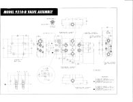
This is the hydraulic schematic shown in the operators manuals for all of the Rural King backhoes.
I'm thinking the highlighted intersection should show as connected and not two separate circuits.
Am I right, or is there something I'm missing? :confused:

(click on thumbnail to enlarge)
HYDRAULIC.PNG
 
   / Backhoe Hydraulic Schematic Incorrect? #2  
I see three errors in that circuit.
One is the error of no tank connection that you have identified.
Second is there is no connection to unload the pump with all of the spools centered. This is based on the presumption that these tractors have fixed displacement gear pumps.
third: None of the valve shifted schematics show the six connections like the center position does. Example on the boom cylinder if you put that valve in float as drawn the pump would dead head.
 
   / Backhoe Hydraulic Schematic Incorrect?
  • Thread Starter
#3  
I see three errors in that circuit.
One is the error of no tank connection that you have identified.
Second is there is no connection to unload the pump with all of the spools centered. This is based on the presumption that these tractors have fixed displacement gear pumps.
third: None of the valve shifted schematics show the six connections like the center position does. Example on the boom cylinder if you put that valve in float as drawn the pump would dead head.
1. Agreed.
2. The pump would unload through the relief valve shown on the tractor side.
3. There are only 4 "connections" per valve "section" in the diagram. The center (unactuated) "section" doesn't have 6 "connections". The diagram is just showing the pressure line connecting the valves. Picture it as overlaid over the valves, not connected to them. The T's represent the 4 "connections" to each valve "section" in the diagram.
 
   / Backhoe Hydraulic Schematic Incorrect? #4  
stny,
2. Unloading across the relief will create unnecessary heat and is potentially damaging to the system and related components.
3. The vast majority of mobile valves show 6 connections in all of the positions even though in reality there may be only connections. This helps show the oil flow path through the valve. The RK schematic is incomplete compared to these.

For reference to both of these issues look at the attached schematic of a two spool husco FEL valve used on by Kubota on some of their tractors.
 

Attachments

  • 9210 schematic.jpg
    9210 schematic.jpg
    316 KB · Views: 157
   / Backhoe Hydraulic Schematic Incorrect?
  • Thread Starter
#5  
stny,
2. Unloading across the relief will create unnecessary heat and is potentially damaging to the system and related components.
3. The vast majority of mobile valves show 6 connections in all of the positions even though in reality there may be only connections. This helps show the oil flow path through the valve. The RK schematic is incomplete compared to these.

For reference to both of these issues look at the attached schematic of a two spool husco FEL valve used on by Kubota on some of their tractors.

Indeed. I stand corrected! Looks like RK and/or TYM has some revising to do of their manuals.
 
   / Backhoe Hydraulic Schematic Incorrect?
  • Thread Starter
#6  
Now that I've actually taken delivery of and used my RK24, I've noticed another problem with this schematic. It shows only 2 hoses between the tractor and backhoe, when in reality there are 3.
 
 
Top