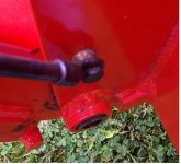
Third and last, showing lower mount point (fuzzy - camera focused on lower pin, I guess).
Here's a quick rundown on parts & method (He used what he had lying around):
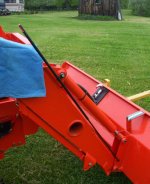
Tube: 3/8" ID, 25" long, with about 1-1/4" of the top split lengthwise and cut off to expose rod (see first picture).
Rod: 5/16", 48" long, cut to 44-1/2" after installation/leveling (others may differ).
Top mount tab: 3/4" bar stock, 2-3/4" long welded to tube. The bucket cylinder pin is drilled and tapped to allow the 1/4" bolt to bottom and not bind the tab.
Lower Rod end: Closed-eye cable connector (like starter motor connector), soldered onto rod (it was copper); 5/16" bolt used because of connector eye size, and bushing described below.
Rod end bushing: Two pieces of tubing. One sized to butt the rod end and hold it away from the bucket bracket, the other to slide through the first, and through the rod end by a small amount. The head of the 5/16" bolt tightens against the end of the smaller, longer tube, sandwiching the rod end between the bolt head and larger, shorter bushing. The bushing tube lengths were sized to stop the bolt flush with the inside of the bucket bracket.
The bottom mount hole (drilled and tapped for the 5/16" bolt) is located 3-1/4" up from the bottom bucket pin, located to be parallel with the loader arm for a clean appearance, and minimum movement of the rod (he didn't want 12" of rod sticking out at the top when the bucket was rolled back).
The top of the rod was marked by setting the tractor on a level surface (road), and cut to make it flush with the tube when the bucket was level. It was painted orange for a few inches for visiblity. If I remember correctly, he didn't have any Kubota orange at the time, and wanted to get the thing installed.
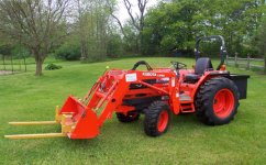
Dad was going for a functional, good looking job. He sort of followed his nose through it, solving problems with what he had at hand. Simplifications may come to mind, but I think he accomplished his goals, don't you?