nickel plate
Veteran Member
Part 1 4/22/2011
Part 2 4/23/2011
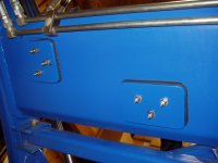
The first two photos are showing the hose run from the left side FEL arm and making two 90 degree turns out on the torque bar. The bulkhead brackets were formed from 3"x4"x1/4" angle stock with all corners radiused. The center bracket has QDs in case I want to remove the grapple from the mounting bar. Again I used black rubber bedliner (I'm so glad I saved it from one of our previously owned trucks) and glue for a waterproof (is there such a thing?) gasket/seal as the brackets are through bolted. I also applied glue in between the bolt heads, washers and nuts. I haven't yet but probably will drill a small weep hole or two in the torque bar just in case. On the bottom of the torque bar are two 3-1/2"x5"x1/4" backing plates also with rubber gaskets and glue.
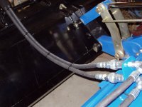
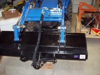
The last two photos show the hose lead from the torque bar to the grapple cylinder. This phase seemed to take foreeever due to the exactness of the hose lengths, enough to still leave some slack when fully curled out yet not drag on the ground when fully curled in. Even before I installed the middle bracket, I bought the hoses with a couple of extra feet on each and experimented every way possible the hoses could be run to the cylinder and eventually came up with what you see. After the final cut and pressing the fittings, I used plastic cable ties in a figure eight to keep the hoses uniform inside of the nylon protection sleeve.
Part 2 4/23/2011
The first two photos are showing the hose run from the left side FEL arm and making two 90 degree turns out on the torque bar. The bulkhead brackets were formed from 3"x4"x1/4" angle stock with all corners radiused. The center bracket has QDs in case I want to remove the grapple from the mounting bar. Again I used black rubber bedliner (I'm so glad I saved it from one of our previously owned trucks) and glue for a waterproof (is there such a thing?) gasket/seal as the brackets are through bolted. I also applied glue in between the bolt heads, washers and nuts. I haven't yet but probably will drill a small weep hole or two in the torque bar just in case. On the bottom of the torque bar are two 3-1/2"x5"x1/4" backing plates also with rubber gaskets and glue.
The last two photos show the hose lead from the torque bar to the grapple cylinder. This phase seemed to take foreeever due to the exactness of the hose lengths, enough to still leave some slack when fully curled out yet not drag on the ground when fully curled in. Even before I installed the middle bracket, I bought the hoses with a couple of extra feet on each and experimented every way possible the hoses could be run to the cylinder and eventually came up with what you see. After the final cut and pressing the fittings, I used plastic cable ties in a figure eight to keep the hoses uniform inside of the nylon protection sleeve.


") I'm surprised you drilled all the way though the torque tube to mount the hose supports. They certainly should take anything you dish out; very stout. I'm also a bit surprised that you chose to route your hoses on the left loader arm instead of along the right arm where the FEL hoses are. I put quick connects in my grapple lines on the left side at the loader post with the loader QCs so I could disconnect the loader and the grapple all from one location. Did you put quick connects at the post on the left loader arm? If you did, you can easily disconnect at the left post as you pull the pin for the loader when you dismount it from the tractor. Either left or right works fine for that.
I'm surprised you drilled all the way though the torque tube to mount the hose supports. They certainly should take anything you dish out; very stout. I'm also a bit surprised that you chose to route your hoses on the left loader arm instead of along the right arm where the FEL hoses are. I put quick connects in my grapple lines on the left side at the loader post with the loader QCs so I could disconnect the loader and the grapple all from one location. Did you put quick connects at the post on the left loader arm? If you did, you can easily disconnect at the left post as you pull the pin for the loader when you dismount it from the tractor. Either left or right works fine for that.