FergFan
Member
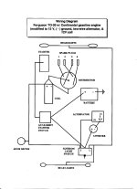
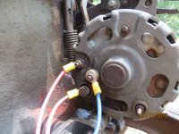
I'm making a wiring harness for an already 12v converted Ferguson TO30 Z129 using a ford 1g alternator. I've read a lot about the delco 10si alternators on here and have seen the wiring diagrams using them. Pretty simple, my concern is the delco and the ford 1g both have a BAT post, however the delco has the P1 and P2 posts...while the Ford 1g has a FLD and GRD posts.
I've been informed I'm to wire my alternator as follows...BAT wired to positive battery terminal on positive battery post...FLD wired through my Voltage regulator(Echlin VR32..has two posts FLD & IGN)and out to my "B" key ignition switch and my GRD grounded at my voltage regulator.
I'm under the opinion the data I'm getting doesn't take the existence of my dash ammeter into consideration, and therefore I can wire my Alternator BAT post to my negative ammeter(discharge) run my positive ammeter(charge) to the "B" post on my key ignition and run a wire from there("B") to the gear shift starter switch. Meaning my FLD alternator post would now run to my "I" key ignition switch.
 Does this sound accurate?
I've been informed I'm to wire my alternator as follows...BAT wired to positive battery terminal on positive battery post...FLD wired through my Voltage regulator(Echlin VR32..has two posts FLD & IGN)and out to my "B" key ignition switch and my GRD grounded at my voltage regulator.
I'm under the opinion the data I'm getting doesn't take the existence of my dash ammeter into consideration, and therefore I can wire my Alternator BAT post to my negative ammeter(discharge) run my positive ammeter(charge) to the "B" post on my key ignition and run a wire from there("B") to the gear shift starter switch. Meaning my FLD alternator post would now run to my "I" key ignition switch.

 Does this sound accurate?