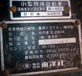
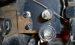
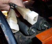
I have owned this tractor for a few years, and it looks like there is some sort of rear remote, maybe 2. I would like to use them if someone can give insight to how to conect a lever, or where to find them. Am posting photo's of S/N and ports and possible valves. Thanks in advance for any help.
You are using an out of date browser. It may not display this or other websites correctly.
You should upgrade or use an alternative browser.
You should upgrade or use an alternative browser.
Hinomoto rear remote
- Thread starter Haroldm
- Start date
- Views: 4598
/ Hinomoto rear remote
#1
kennyd
Advertiser
Welcome to TBN
It sure does look like some type of electric/hydraulic valve, but I am not familiar enough with your machine to provide any help, hopefully someone here is.
It sure does look like some type of electric/hydraulic valve, but I am not familiar enough with your machine to provide any help, hopefully someone here is.
Bump, I'm still looking for help with this. the 2 (valves?) are directly in front and above the 4 ports 2 ports have QD's that are male/female instead of both female like all American tractors I've been around. the 2 gang plugs have 4 male spade terminals inside. Oh, the QD's are rather small, maybe for 1/4 or 3/8ths hoses. If no one hase info here, maybe you can set a ballpark figure on PSI's. I could try testing with a ohmmeter and pressure gauge if I can connect the valves up.
Harold
Harold
J_J
Super Star Member
- Joined
- Sep 6, 2003
- Messages
- 18,952
- Location
- JACKSONVILLE, FL
- Tractor
- Power-Trac 1445, KUBOTA B-9200HST
That setup, looks like it was designed for an attachment that probably had solenoid valves to control the hydraulics. Although I see two solenoid valves, I see only one set of outputs. Do you have any switches on the FEL lever handle? I believe the male QD is the pressure fitting, and the female the return line. . Plug a gage on it and see if it has pressure, and find a switch that might apply power to the electrical plugs. I am guessing that you don't have a manual.
Scotty370
Platinum Member
- Joined
- Dec 18, 2008
- Messages
- 896
- Location
- Buffalo, New York
- Tractor
- 318 John Deere, 4200 John Deere, 1947 John Deere "M"
Limited help here. Can find parts manuel only at:
Hinomoto Tractor Manuals, Hinomoto Parts Manuals
TractorData.com - Hinomoto E2804 tractor data
Seems this Japanese tractor manufacture had several owners! ~S
Hinomoto Tractor Manuals, Hinomoto Parts Manuals
TractorData.com - Hinomoto E2804 tractor data
Seems this Japanese tractor manufacture had several owners! ~S
Thanks Scotty for the link to the parts book. As to the Tractor Data site, the info there is a little suspect, as the 28 PS on my data plate translates to about 27.5 HP.
JJ: there are 2 pipe plugs next to the QD's that are in line with the selonoid on the rt. in the other pic. Are you saying the HYD is one way? The loader that is attached has 2 way Hyd. Haven't a clue as to what to expect for PSI. but will try something. Was hoping someone would have a more educated guess than I. Thank you for the help.
Harold
J_J
Super Star Member
- Joined
- Sep 6, 2003
- Messages
- 18,952
- Location
- JACKSONVILLE, FL
- Tractor
- Power-Trac 1445, KUBOTA B-9200HST
Thanks Scotty for the link to the parts book. As to the Tractor Data site, the info there is a little suspect, as the 28 PS on my data plate translates to about 27.5 HP.
JJ: there are 2 pipe plugs next to the QD's that are in line with the solenoid on the rt. in the other pic. Are you saying the HYD is one way? The loader that is attached has 2 way Hyd. Haven't a clue as to what to expect for PSI. but will try something. Was hoping someone would have a more educated guess than I. Thank you for the help.
Harold
A one way solenoid usually has only one solenoid, to control fluid as in an on/off situation. A two way solenoid valve can switch hyd flow direction. You do have two sets of remotes, one set has QD's, and the other set is plugged. You could add some QD's instead of the plugs.
Without a schematic, it will be hard to determine the wiring, but in any case, you could go direct to the solenoid and apply 12v to the two wires on the solenoid to activate. As far as pressure, it will probably be tractor pressure. In order to test the pressure at the remotes, you would need to activate the solenoids.
You might try and trace the wires on the solenoid back to the plugs and see if the plug is used to apply power to the solenoid. The plugs might be for something else.
Can you think of an implement offered by the tractor manufacture that might use a hyd circuit? The electrical plugs might even be part of a feed back circuit for what the implement is doing.
To test pressure, just plug a gage in one of the loader QD's and activate the valve until it starts to relieve.
I have a device that I use to trace wiring. You connect to the wire you want to trace, and it transmit a signal. The receiver looks like a ball pen, and you hold the receiver to any wire bundle and can trace any wire on the tractor, or auto. You have to use some logic when two wires are attached to the same terminal. but you can eventually map out the electrical system.
The hyd outlets might be used for cyl, or hyd motors.
Last edited:


