downsizingnow48
Elite Member
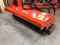
Quite a while ago I got a ditch and bank mower. Bestsco AGL145. Several members cautioned me up front that it was too big for my B21. When it arrived I could see at a glance they were right. Too much weight, too far back, and especially out to the side. It would be ok when the roller is on the ground, but not ok at all when transporting and positioning, with the mower up in the air. I needed that mower to groom the property the way I want it to look. Getting a bigger tractor was not in the cards. So I set the mower aside and thought about it for a while.
I decided to make a set of hydraulic operated transport wheels. With the wheels down, the weight of the mower would not destabilize the tractor or put excess force on the three point hitch while moving around the property. With the wheels up, the mower would operate on the roller in the usual way.
I got the modifications done earlier today and pulled it out in the yard to test out the movements of the mower and wheels. Everything is fine. The photos below show some of the fabrication details.
Photo 1. I made side plate extensions out of 3/8 x 5 1/2 flat bar, attached to the mower side plates with six 1/2" bolts. The wheel mounting bar is 3/16 x 4 square tube, with 1/4" end plates that bolt to the side plate extensions.
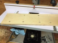
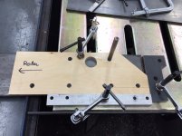
Photo 2, 3. I used a piece of furniture grade birch plywood to make an accurate template so all 24 of the holes would line up.
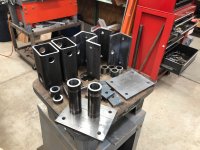
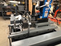
Photo 4. Showing the pieces of the wheel mounts. The assembly is clamped to the mounting bar with 3/8" material. The wheel yoke is 1/4 x 3 x 4 rectangular tube.
Photo 5, 6. Drilling holes in the yokes. Welding up the yokes.
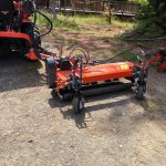
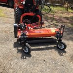
Photo 7, 8, 9. Showing the mower in various positions. It uses 4 valves for wheels, upper link, tilt cylinder, and side extension cylinder.
I decided to make a set of hydraulic operated transport wheels. With the wheels down, the weight of the mower would not destabilize the tractor or put excess force on the three point hitch while moving around the property. With the wheels up, the mower would operate on the roller in the usual way.
I got the modifications done earlier today and pulled it out in the yard to test out the movements of the mower and wheels. Everything is fine. The photos below show some of the fabrication details.
Photo 1. I made side plate extensions out of 3/8 x 5 1/2 flat bar, attached to the mower side plates with six 1/2" bolts. The wheel mounting bar is 3/16 x 4 square tube, with 1/4" end plates that bolt to the side plate extensions.
Photo 2, 3. I used a piece of furniture grade birch plywood to make an accurate template so all 24 of the holes would line up.
Photo 4. Showing the pieces of the wheel mounts. The assembly is clamped to the mounting bar with 3/8" material. The wheel yoke is 1/4 x 3 x 4 rectangular tube.
Photo 5, 6. Drilling holes in the yokes. Welding up the yokes.
Photo 7, 8, 9. Showing the mower in various positions. It uses 4 valves for wheels, upper link, tilt cylinder, and side extension cylinder.