Are you talking about the stand-alone tach/hour meter that is not part of the newer style integrated instrument clusters?
Do you not have the existing sensor and tach?
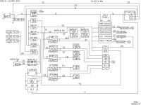
I have schematics for both styles but they do not show pin-outs at the instruments, only generic wire paths. they show the sensor connected to the tach but no more detail than that. See attached files:
Guessing that there is a light that comes on with the other dash lights we can maybe figure it out by the letters, this is my best guess (I have the integrated cluster so nothing to look at)
G=Ground
S=Switch (hot when in run position)
I=Illumination
K=Crank sensor
If I remember correctly the sensor actually is a pickup coil that is triggered off of the flywheel ring gear teeth. I have seen specs on setting the correct clearance between the sensor and the teeth. Also I believe the sensor is grounded through the housing. If yours is not functioning I would check the threads to make sure they are clean and have good contact with the block, then screw the housing in until it touches the ring gear, then back it out a turn and make sure that it clears all the teeth before starting. To get really fancy, you could set up a dial indicator in the hole and find the max run-out and use that as the high point for setting the sensor.
If your wiring harness is intact and you know which wire goes to the sensor a continuity check will show which wire at the tach comes from the sensor.
Hope this helps,