tatra805
Silver Member
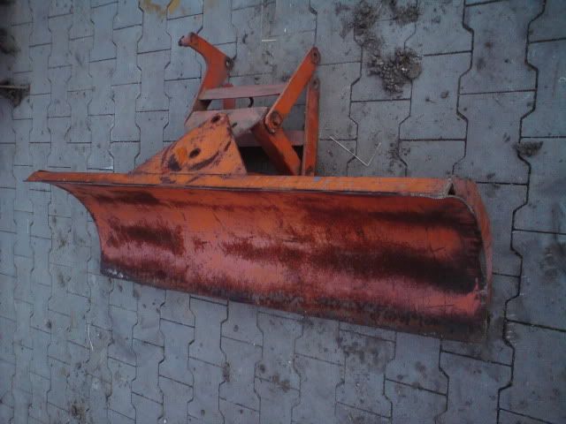
Started with my backblade
The blade itself comes from some non complete front mount blade i found together with the tillers i bought last weekend.
Matches the width of the iseki perfectly.
I already sourced a pivot point from some dismantled assembling robot. That with the angle setting plates of the front mount blade give me the possibility to have both the beam and the blade to be settable.
The beam is +30/-30 settable which moves the center of the blade from in-line with the left backwheel to inline with the right backwheel.


The beam has a tube welded in where the pivot pin runs through, the plates are all 10mm thickness so i hope and expect things to be beefy enough to handle the pull forces.

I used the other pivot, which rotates 180, as it really is a heavy piece with load bearing pivot pin and needle bearings for the rotating which will handle the stresses from the bottom mounted blade much better. The blade can then be set to any angle using a hydraulic cylinder.
missing picture to follow.
As an extra i build in a rotating point for the blade so it also can be set at an angle or float when a tire hits a pothole or something. I guess this will be the weakest point and therefore used some pressure spreading plates and a longer guiding tube wich have to take the lateral forces (bending) while a M20 rod takes the axial forces (pulling).
To explain a litte: both plates have tubes welded on. On the picture you only see the tube of the right side plate. (biggest piece of tube is tubes to beef it up). The left side plate has a smaller diameter tube which runs inside the smallest tube of the right side plate.
Through this tube a M20 rod runs from the threaded pivot point base plate (20mm thick) to the exit of the tube in tube where it is tightened with the nut you see in the picture.

I will not have the possibility to push backwards with the blade but consider it a lesser issue as i still have the fell bucket to push things forward.
I'll update as things progress. still a couple of evenings to finish the construction.
tell me what you think, all input appreciated
")
The blade itself comes from some non complete front mount blade i found together with the tillers i bought last weekend.
Matches the width of the iseki perfectly.
I already sourced a pivot point from some dismantled assembling robot. That with the angle setting plates of the front mount blade give me the possibility to have both the beam and the blade to be settable.
The beam is +30/-30 settable which moves the center of the blade from in-line with the left backwheel to inline with the right backwheel.
The beam has a tube welded in where the pivot pin runs through, the plates are all 10mm thickness so i hope and expect things to be beefy enough to handle the pull forces.
I used the other pivot, which rotates 180, as it really is a heavy piece with load bearing pivot pin and needle bearings for the rotating which will handle the stresses from the bottom mounted blade much better. The blade can then be set to any angle using a hydraulic cylinder.
missing picture to follow.
As an extra i build in a rotating point for the blade so it also can be set at an angle or float when a tire hits a pothole or something. I guess this will be the weakest point and therefore used some pressure spreading plates and a longer guiding tube wich have to take the lateral forces (bending) while a M20 rod takes the axial forces (pulling).
To explain a litte: both plates have tubes welded on. On the picture you only see the tube of the right side plate. (biggest piece of tube is tubes to beef it up). The left side plate has a smaller diameter tube which runs inside the smallest tube of the right side plate.
Through this tube a M20 rod runs from the threaded pivot point base plate (20mm thick) to the exit of the tube in tube where it is tightened with the nut you see in the picture.
I will not have the possibility to push backwards with the blade but consider it a lesser issue as i still have the fell bucket to push things forward.
I'll update as things progress. still a couple of evenings to finish the construction.
tell me what you think, all input appreciated


