Freakingstang
Gold Member
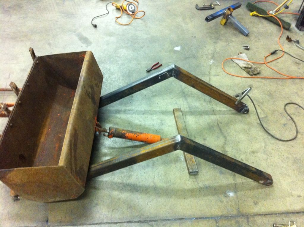
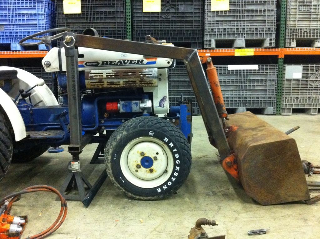
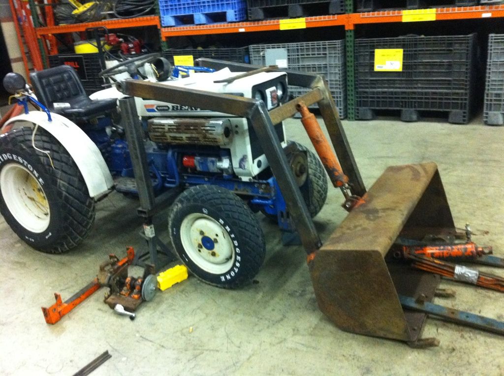
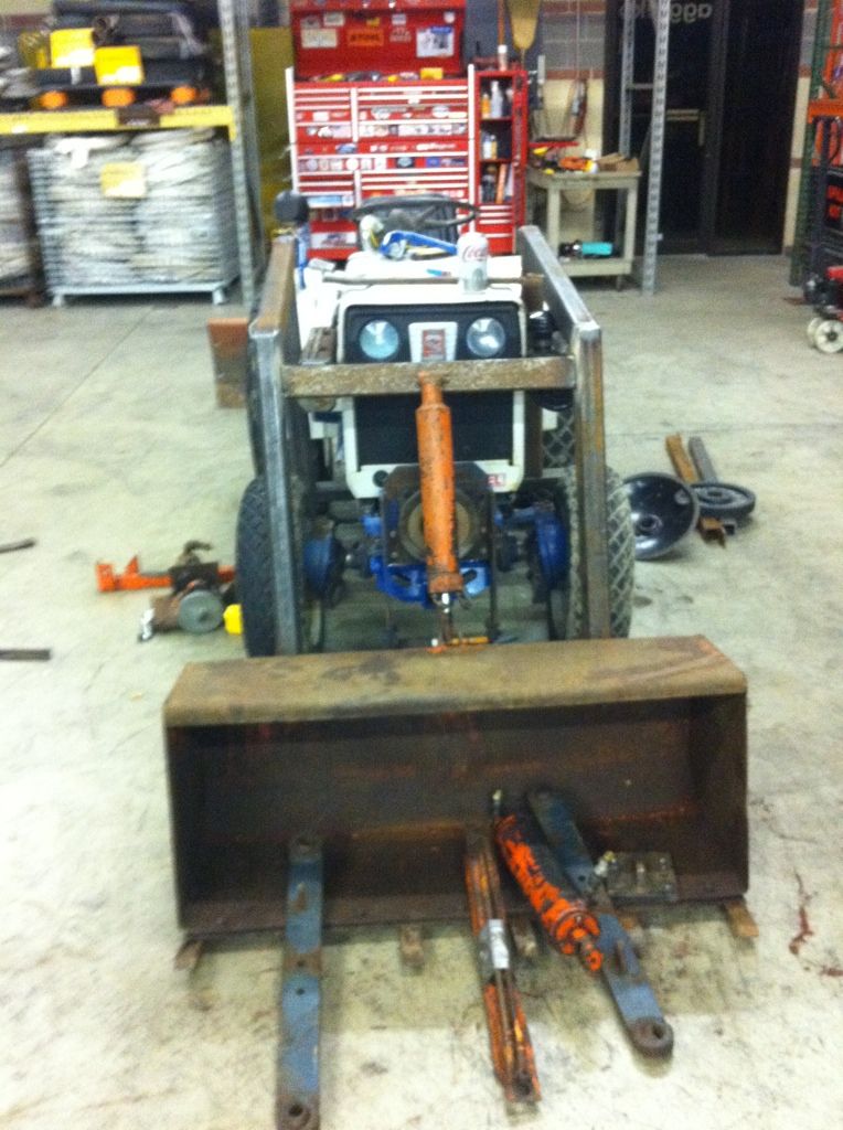
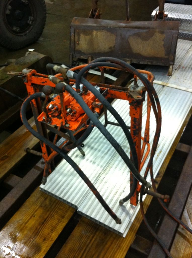
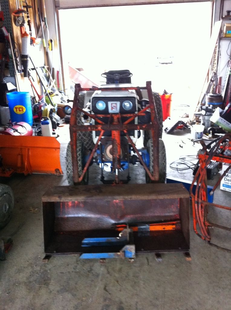
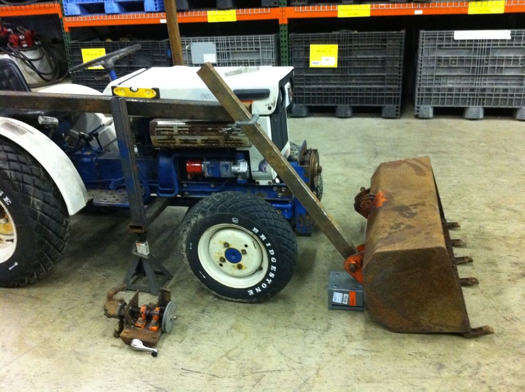
Did some wheelin' and dealin' over the last couple weeks and ended up with this loader setup off of an old economy tractor. I believe it was home made at some point in time... It was a complete setup with hydraulics, hyd tank, pump, cylinders, spool valves and hoses. The bucket is 42" wide and seems like a perfect match for the little beaver.
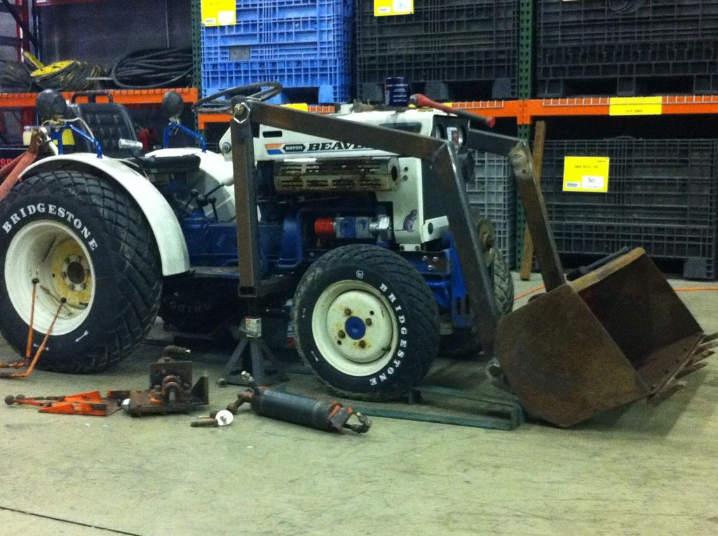
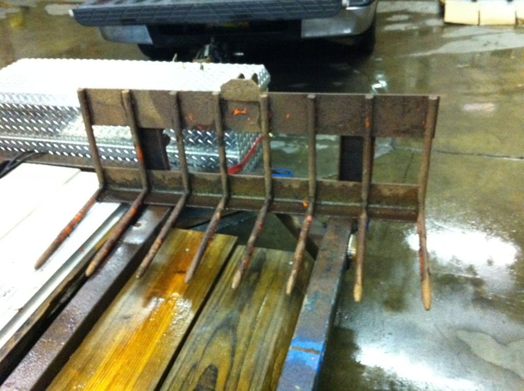
even got a set of hayforks with it. I'll eventually make a grapple for this so I can use it to move brush and trees around.
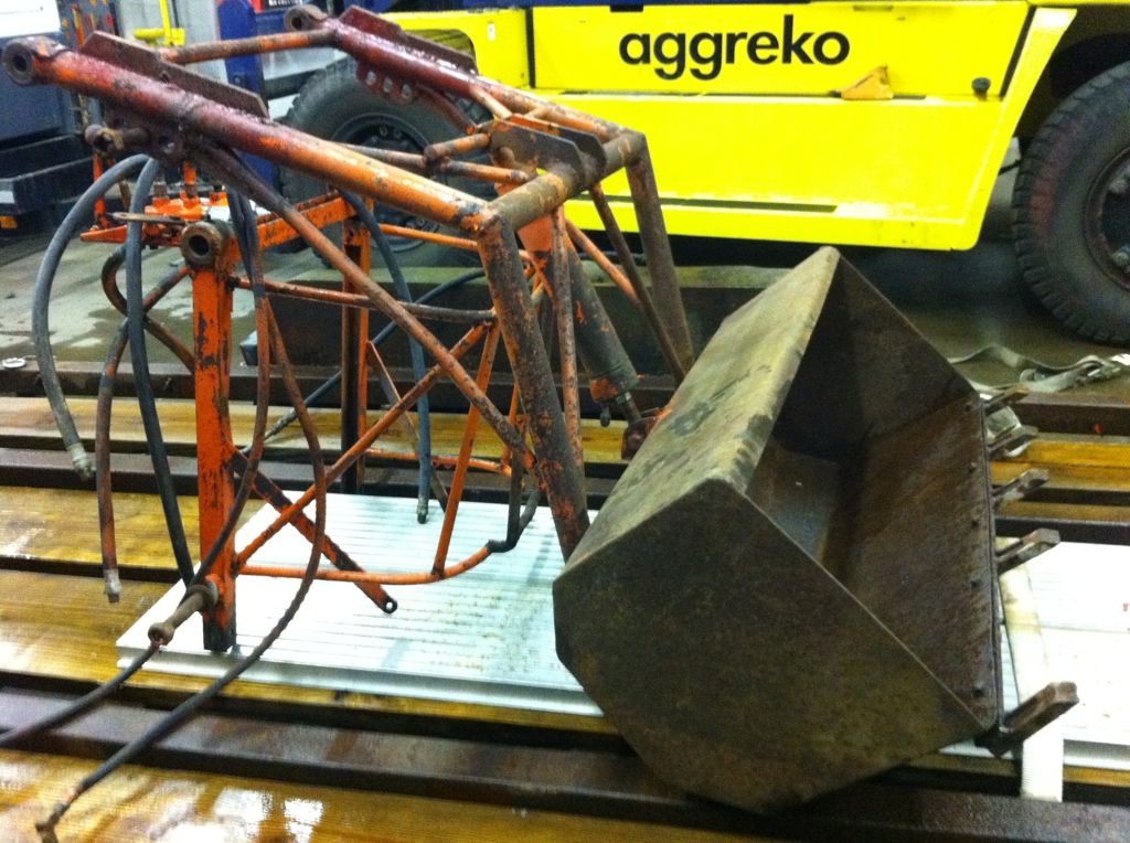
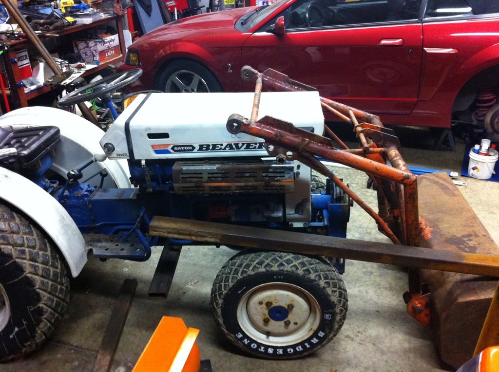
instead of trying to modify what was there....I just started over....
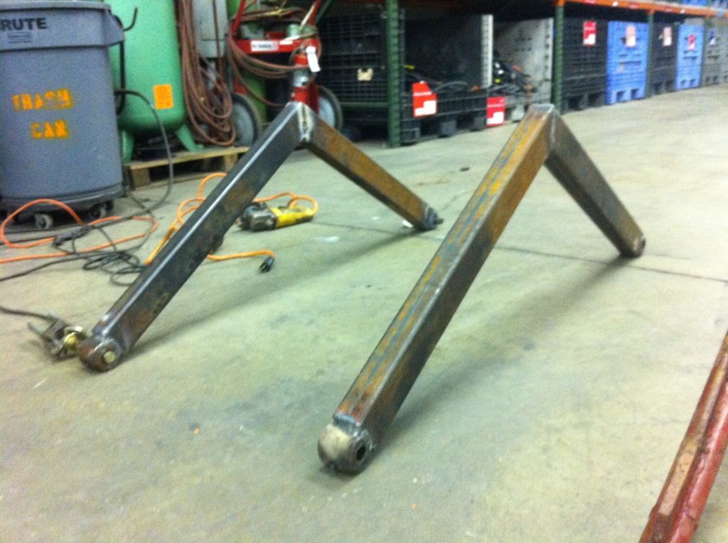
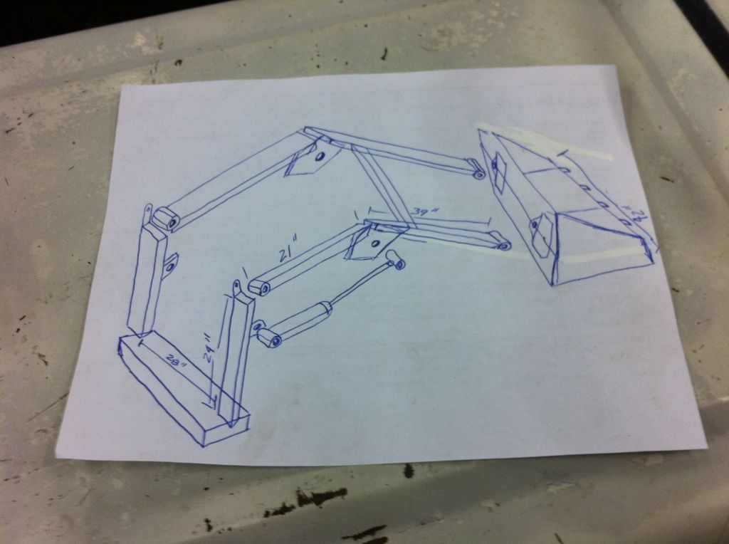
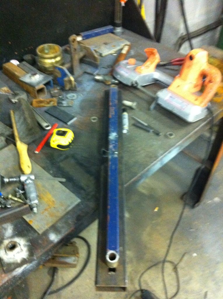
I did resuse the sleeved bushings off of the old loader frame.... Here are my sophisticated set of Freakin' plans...lol
here is the start of the mockup....I used some 2x4's to get the propper angles...(no pics, sorry) easier and cheaper trial and error with free 2x4's...
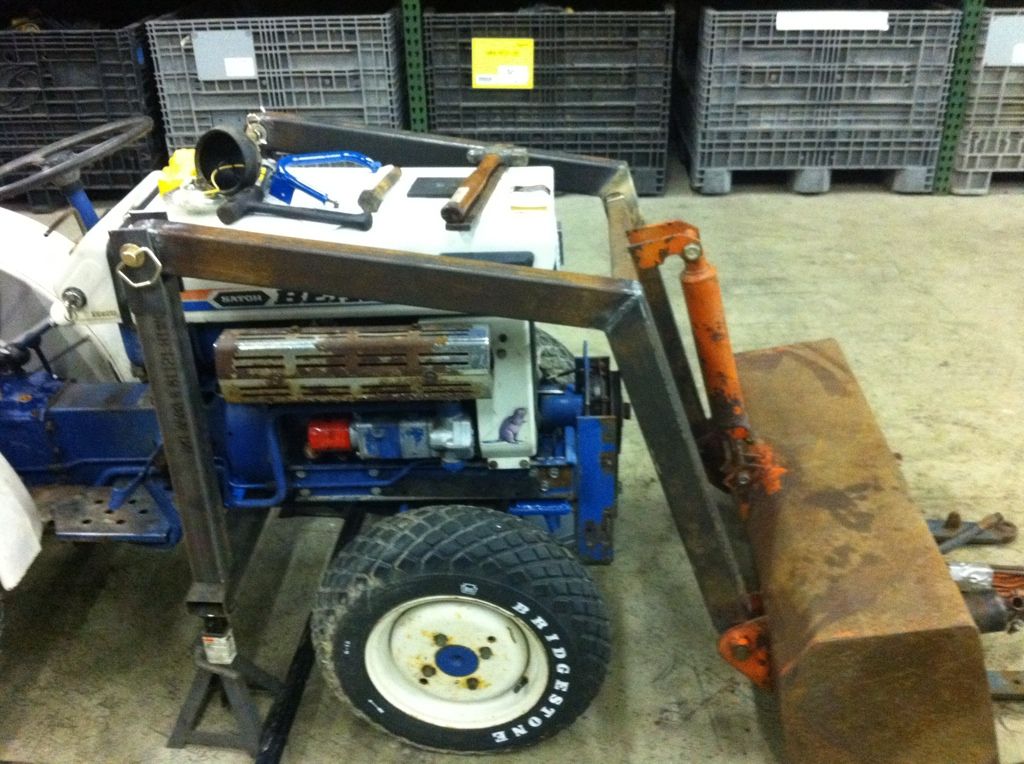
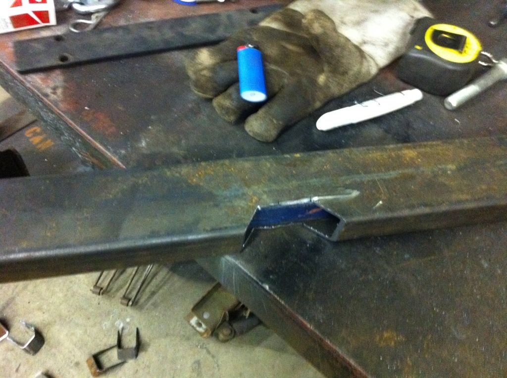
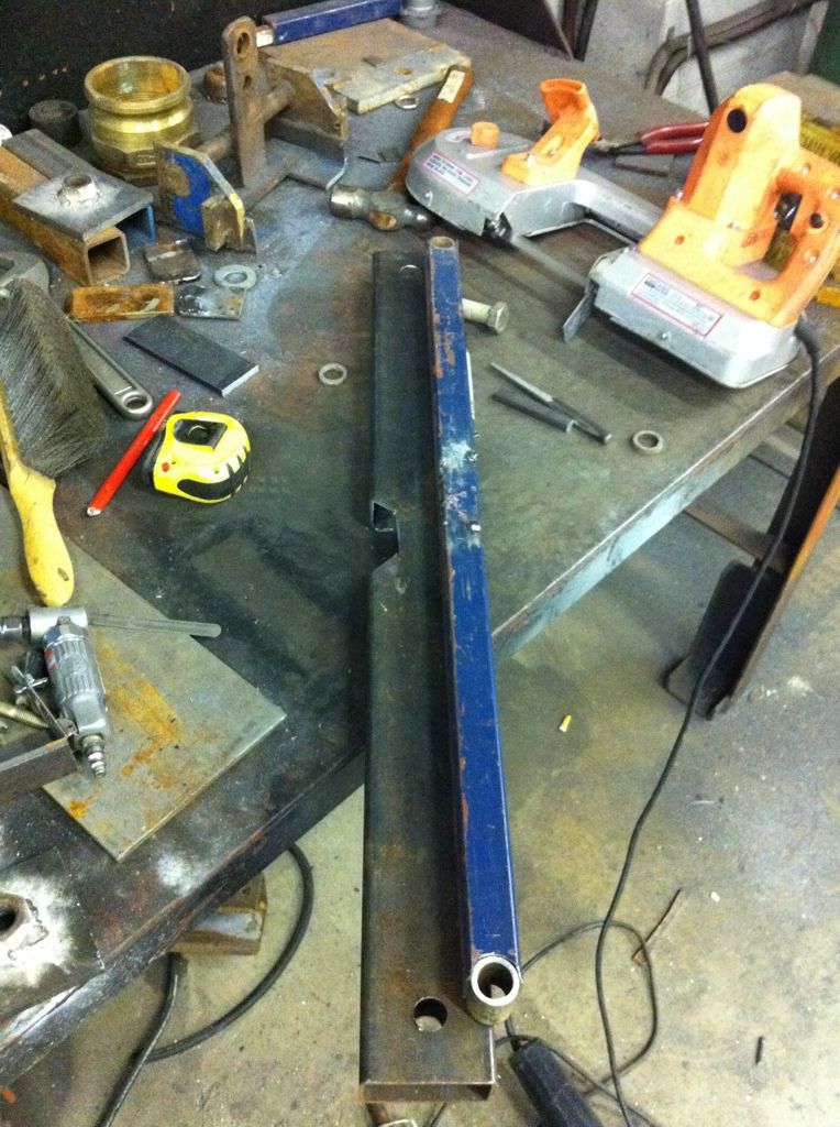
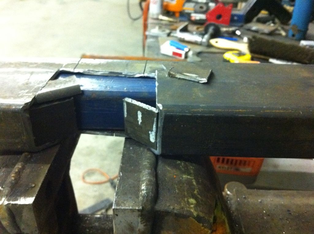
I started with a 32" piece of 1 1/2" x 3" tubbing as the cross beam for the uprights. This is what the uprights and rear sub frame will hook into. This tubing is 3/16" wall. I then took a piece of 1" box tube, 1/4" wall and slid it inside. I did this to maximize support and minimize clearance issues as the cross beam will sit between the trans tunnel and the driveshaft. I did this to utilize ground clearance. I made a wide "V" notch in the center of the tube for clearance on the drain plug of the bellhousing. It will be fully reinforced and boxed back in before it is all said and done
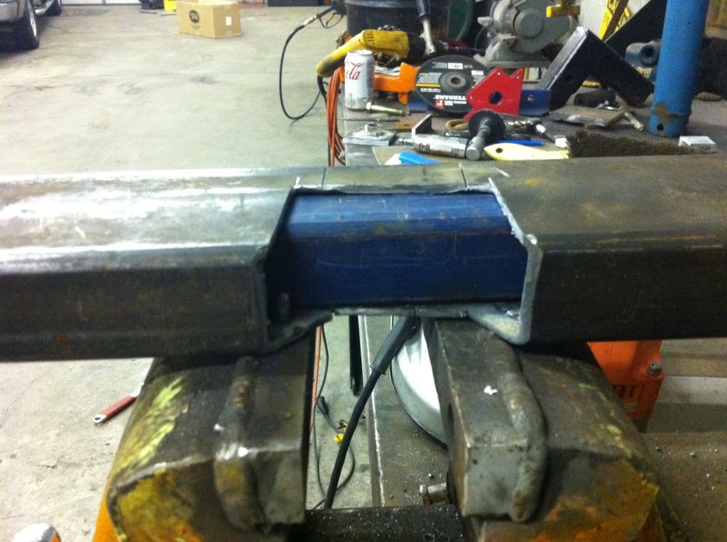
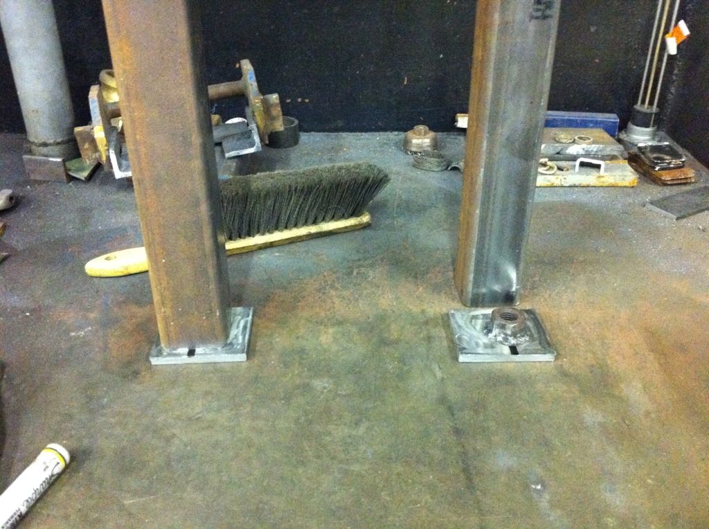
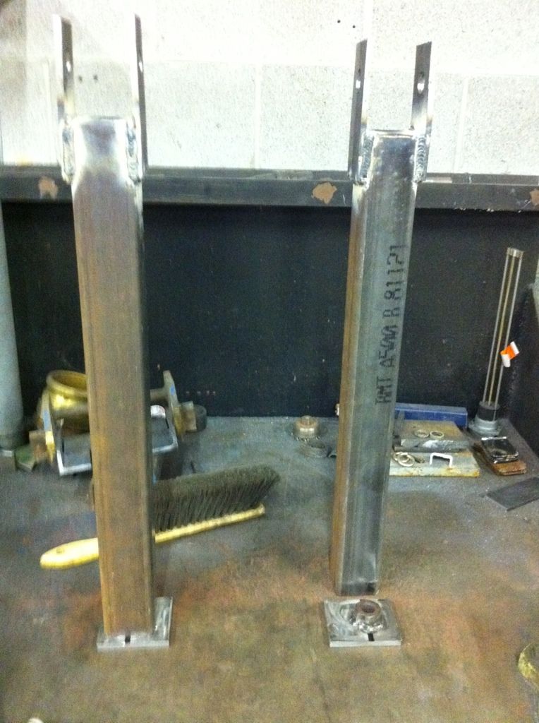
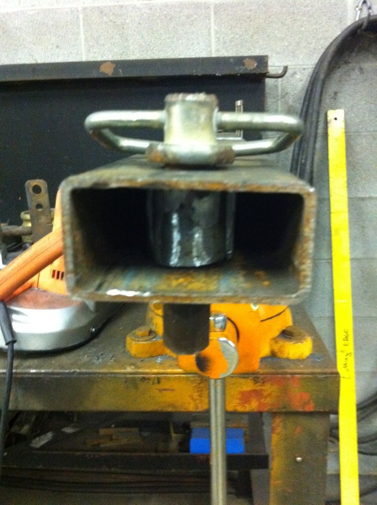
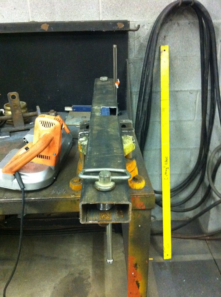
then, after much measuring and spacing, I decided to make the uprights removable. I cut some 1" ID tube and notched the inner support tube to act as a sleeve for the 1" bolt that will come up through the bottom into the upright posts.
even got a set of hayforks with it. I'll eventually make a grapple for this so I can use it to move brush and trees around.
instead of trying to modify what was there....I just started over....
I did resuse the sleeved bushings off of the old loader frame.... Here are my sophisticated set of Freakin' plans...lol
here is the start of the mockup....I used some 2x4's to get the propper angles...(no pics, sorry) easier and cheaper trial and error with free 2x4's...
I started with a 32" piece of 1 1/2" x 3" tubbing as the cross beam for the uprights. This is what the uprights and rear sub frame will hook into. This tubing is 3/16" wall. I then took a piece of 1" box tube, 1/4" wall and slid it inside. I did this to maximize support and minimize clearance issues as the cross beam will sit between the trans tunnel and the driveshaft. I did this to utilize ground clearance. I made a wide "V" notch in the center of the tube for clearance on the drain plug of the bellhousing. It will be fully reinforced and boxed back in before it is all said and done
then, after much measuring and spacing, I decided to make the uprights removable. I cut some 1" ID tube and notched the inner support tube to act as a sleeve for the 1" bolt that will come up through the bottom into the upright posts.