quarencia
Silver Member
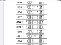
Does anyone know what this schematic means and can you explain it to me?
I'm adding a couple of proportional solenoid valves to the Bota and am having some trouble understanding this valve position schematic. I've never seen transition or crossover blocks showing metered flow paths during valve transition. I'm not sure exactly what this is telling me, but I suspect it's important to my purpose.
I'm trying to understand if I need to get configuration 008 or 009 in the below picture. I need a valve that has pressure to tank in neutral and pa-tb and pb-ta in the left or right positions. But I don't fully understand the meaning of the transition blocks (The second and fourth blocks in each configuration). I know these are showing how the valve behaves during transition from center position to either off-center position. I do not understand what the valve behavior will actually be based on the diagram. I have a guess at what they mean, but I'll keep my mouth shut and avoid confirming my stupidity and see if anyone here actually knows.

Note 1 for configurations 008 and 009 says "consider specific spool position"...so that's helpful. This is the link to the Parker document where this picture came from https://www.parker.com/Literature/I...atalogues/Industrial Valves UK/02/D1VW UK.pdf
Any good thoughts?
I'm adding a couple of proportional solenoid valves to the Bota and am having some trouble understanding this valve position schematic. I've never seen transition or crossover blocks showing metered flow paths during valve transition. I'm not sure exactly what this is telling me, but I suspect it's important to my purpose.
I'm trying to understand if I need to get configuration 008 or 009 in the below picture. I need a valve that has pressure to tank in neutral and pa-tb and pb-ta in the left or right positions. But I don't fully understand the meaning of the transition blocks (The second and fourth blocks in each configuration). I know these are showing how the valve behaves during transition from center position to either off-center position. I do not understand what the valve behavior will actually be based on the diagram. I have a guess at what they mean, but I'll keep my mouth shut and avoid confirming my stupidity and see if anyone here actually knows.

Note 1 for configurations 008 and 009 says "consider specific spool position"...so that's helpful. This is the link to the Parker document where this picture came from https://www.parker.com/Literature/I...atalogues/Industrial Valves UK/02/D1VW UK.pdf
Any good thoughts?
