Sorry for the long post. I recently picked up a number of hydraulic components in a lot batch including pumps, spool valves, cylinders and in particular a "hyd. power unit" that I have some questions about.
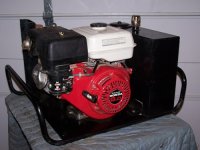
The power unit has a Honda GX240 (8hp) motor, coupled to a pump (unknown spec's), a 5 gal. reservior, 2 spool valves and a couple of pressure relief valves.
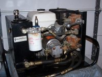
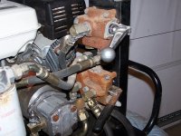
My question is on the pluming of the two valves--both are provided high pressure from the pump. One (lower) is open center with hoses to dual action cylinder. The other (top) appears to be open until actuated, then closes, which in effect increases the pressure to the 1st one. The 2nd (top) has only one action on the handle. Spring loaded to "open" position.
Is this a "Rube Goldberg" way of doing something (two stages of pressure) that could be accomplished with another means. I don't have a pressure guage to check pressure, but watching hose flex during operation of the unit, if you run a cylinder to the end of it's travel and then (while holding lower valve actuated, you actuate the top valve, much more pressure is applied to the cylinder. (return pressure to the tank is blocked, thus increasing cylinder pressure through the lower spool valve).
These components came from the engineering dept. of Veermer Corp. (heavy equip Mfr.) so who knows what they were attempting to accomplish.
I want to use the power unit for a log splitter in work. In the batch I've identified a few items, 2 single spool Danfoss valves, a 3 spool Danfoss valve, a Prince flow control, and I've got about 10 pumps of various mfr's that I'm trying to identify. I'll probably reconfigure the valving for my spitter, but was wondering if any users had comments on the way it currently is set up. Attached are some JPEG pic's of the unit and a crude diagram of plumbing.
The power unit has a Honda GX240 (8hp) motor, coupled to a pump (unknown spec's), a 5 gal. reservior, 2 spool valves and a couple of pressure relief valves.
My question is on the pluming of the two valves--both are provided high pressure from the pump. One (lower) is open center with hoses to dual action cylinder. The other (top) appears to be open until actuated, then closes, which in effect increases the pressure to the 1st one. The 2nd (top) has only one action on the handle. Spring loaded to "open" position.
Is this a "Rube Goldberg" way of doing something (two stages of pressure) that could be accomplished with another means. I don't have a pressure guage to check pressure, but watching hose flex during operation of the unit, if you run a cylinder to the end of it's travel and then (while holding lower valve actuated, you actuate the top valve, much more pressure is applied to the cylinder. (return pressure to the tank is blocked, thus increasing cylinder pressure through the lower spool valve).
These components came from the engineering dept. of Veermer Corp. (heavy equip Mfr.) so who knows what they were attempting to accomplish.
I want to use the power unit for a log splitter in work. In the batch I've identified a few items, 2 single spool Danfoss valves, a 3 spool Danfoss valve, a Prince flow control, and I've got about 10 pumps of various mfr's that I'm trying to identify. I'll probably reconfigure the valving for my spitter, but was wondering if any users had comments on the way it currently is set up. Attached are some JPEG pic's of the unit and a crude diagram of plumbing.