VOLTAGE REGULATOR DIAGNOSTIC DIAGRAM--NEED HELP READING!

   / VOLTAGE REGULATOR DIAGNOSTIC DIAGRAM--NEED HELP READING! #1  

npalen

Elite Member
Joined
Nov 17, 2009
Messages
3,478
Location
Beloit, KS
Tractor
Kubota B9200 HSTD and Mahindra 3015
Scan0001.jpg
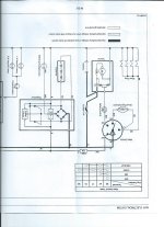
Could use some help in understanding this page from the B9200 Shop Manual.
I'm trying to test the voltage regulator as the charging system doesn't seem to be working. I did check the alternator (dynamo in Kubotese) output which appears to be fine with more than 20 VAC. Anyways, referring to the attached, the diagram in the upper left shows the wire colors as they exist on the connector but don't match the wire colors on the regulator. The colors on the regulator are as shown here: kubota b9200 voltage | eBay
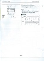
So in testing with an ohm meter, is "Check Table" on the right side of the shop manual page telling me to check between a terminal on the coupler and it's corresponding terminal on the regulator or what?
All help is appreciated. Hate to spend $135 on a new regulator without being sure that is the problem.
 
   / VOLTAGE REGULATOR DIAGNOSTIC DIAGRAM--NEED HELP READING!
  • Thread Starter
#2  
After thinking about this a little more: I'm guessing that I'm supposed to "transfer" the wire colors on the connector to the regulator ignoring the actual wire colors on the regulator. If that's the case, my question then is in regard to the "Check Table" where it shows "Tester + terminal" and "Tester - terminal". I'm assuming the reason for using the polarity connected as shown is because of diodes in the regulator? I don't recall ever being concerned about the positive and negative connections (edit: when checking resistance) on the VOM but maybe this is a first for me.
 
   / VOLTAGE REGULATOR DIAGNOSTIC DIAGRAM--NEED HELP READING! #3  
I think they are telling you to check the resistances between the leads of the regulator. See below for edit.
 
   / VOLTAGE REGULATOR DIAGNOSTIC DIAGRAM--NEED HELP READING! #4  
I think they are telling you to check the resistances between the leads of the regulator. Yes there are diodes and other semiconductors in there.
 
   / VOLTAGE REGULATOR DIAGNOSTIC DIAGRAM--NEED HELP READING!
  • Thread Starter
#5  
Thanks for the reply, BobRip.
I did notice a couple of things while troubleshooting: The fanbelt was a little loose which probably wasn't helping the charging and also I noticed that the contacts inside the voltage regulator connector appeared to be fairly corroded. Can I simply spray some aerosol contact cleaner on the terminals and expect that to "do the job" of making sure I'm getting good connections? Regardless, I will go back and do the check on the regulator using the "Check Table" in the morning.
I did notice after reconnecting the regulator and turning the "ignition" switch on that the battery "idiot" light came on which normally doesn't happen. However, after turning the switch off and then back on the battery light did not come on. Maybe this is an indication of at least one bad connection due to the corrosion mentioned above?
I barely qualify as a "shade tree mechanic" so do appreciate any and all feedback.
 
   / VOLTAGE REGULATOR DIAGNOSTIC DIAGRAM--NEED HELP READING! #6  
Thanks for the reply, BobRip.
I did notice a couple of things while troubleshooting: The fanbelt was a little loose which probably wasn't helping the charging and also I noticed that the contacts inside the voltage regulator connector appeared to be fairly corroded. Can I simply spray some aerosol contact cleaner on the terminals and expect that to "do the job" of making sure I'm getting good connections? Regardless, I will go back and do the check on the regulator using the "Check Table" in the morning.
I did notice after reconnecting the regulator and turning the "ignition" switch on that the battery "idiot" light came on which normally doesn't happen. However, after turning the switch off and then back on the battery light did not come on. Maybe this is an indication of at least one bad connection due to the corrosion mentioned above?
I barely qualify as a "shade tree mechanic" so do appreciate any and all feedback.

Spray plenty of contact cleaner in the connector then quickly plug it in and out repeatedly (all with power off). The idea is to try and get rid of any oxidation on the contacts by a combination of chemical and mechanical action. Now try it and see if you get that battery light each and every time.

Next, carefully examine the contacts to see if one or more are bent a bit out of line with the others. If you find one or more like that, they (or it) may not be making good solid contact with their (or its) opposite number. If you find something like this, reach in with an appropriately sized tool (such as a flat screwdriver) and gently prise the offending contact(s) back into position. Try it again.
 
   / VOLTAGE REGULATOR DIAGNOSTIC DIAGRAM--NEED HELP READING! #7  
The WSM sure didn't give you a lot to go on. I bet fixing the corroded connectors like mentioned above will help you out. If not, thought I would throw a few thoughts out there to help make sense of this WSM regulator test. All testers have a high impedance connection in them, so any would work for your measurement. The reason that they are saying "use a high-resistance tester as far as possible," is that the higher the impedance, the more precise the measurement is. As you may know, a resistor reduces the flow of current through it. If the resistor is large enough, then there will be almost know current though it. This keeps the tester from being damaged by any current if you are testing a "hot" system. If current does flow through it, then the tester could be damaged and the measurement, at the least, will not be accurate.

Oh, impedance and resistance should be used interchangeably here. In DC systems like a tractor/car they mean exactly the same thing. The correct industry lingo used though is impedance whether it's AC or DC, but we can chalk this up to Jinglish. In an AC system like a house, impedance takes into account both the resistance and reactance (kinda like feedback due to inductance and capacitance created from the AC power oscillating back and forth) in the circuit. I will leave it at that because I don't want to derail this.

Also, about the orientation of the + and - probes of the tester, you are right. Normally this has no impact when checking continuity, except if diodes were used. Diodes block the flow of current in one direction until you apply so much power that they break down and then current flows across in a direction that it was not meant to. During a continuity test, the tester will output a small charge to check the continuity. It's only going to flow in one direction, so the orientation in the WSM is to make sure that you are lined up correctly with the direction of the diodes. Hope this helps make sense of the WSM a little bit more.
 
   / VOLTAGE REGULATOR DIAGNOSTIC DIAGRAM--NEED HELP READING! #8  
Yes right on the terminal connector for rectifier. In electric world language it consists basically of 4 diodes in a triagle to convert AC from alternator to DC for your tractor lights/power use. With tractor off- If you are using the digital meter, set it on the diode setting or the only one setting by itself with arrow. the off means its stays zero, no change in reading. on means the numbers change higher then zero. If the readings still matches the chart - you might want to take notes of the "on" readings numbers. sometimes you might have one side going bad so the WHOLE regulator needs to be replaced anyways.
 
   / VOLTAGE REGULATOR DIAGNOSTIC DIAGRAM--NEED HELP READING!
  • Thread Starter
#9  
Scan0002.jpg

EDIT: Next post shows scan right side up.

Here's a scan of the voltage regulator. I took readings with VOM (both resistance and diode more) and found several discrepancies compared to the Check Table in post #1 above. For instance going from (+)red to either (-) blue I was seeing a little over 5 megohms. (Should be an "off" condition according to chart) Going from (-) red to (+) either blue or white gave an "off" reading instead of the "on" shown in the Check Table.
I did take the opportunity to clean the contacts but looks like I'm needing a new regulator. Removing the (+) battery cable and then taking a voltage reading from it to ground indicated zero VDC.
 
   / VOLTAGE REGULATOR DIAGNOSTIC DIAGRAM--NEED HELP READING!
  • Thread Starter
#10  
scan0003.jpg

Here's the scan shown right side up.
 

Tractor & Equipment Auctions

Pump (A46683)
Pump (A46683)
2012 Cadillac SRX SUV (A46684)
2012 Cadillac SRX...
5TH WHEEL PLATE W/RAIL (A47001)
5TH WHEEL PLATE...
2009 KENWORTH T800 (A47001)
2009 KENWORTH T800...
2012 PARK SEPARATOR (A47001)
2012 PARK...
PCC CONNECTIONS (A47001)
PCC CONNECTIONS...
 
Top