jeff9366
Super Star Member
- Joined
- Jan 14, 2011
- Messages
- 12,777
- Tractor
- Kubota Tractor Loader L3560 HST+ ~~~~~~~~~~~~~ 3,700 pounds bare tractor, 5,400 pounds operating weight, 37 horsepower
This is my second Woodward Crossing Tool Bar Cultivator assembly. I am going to show how one assembles from the two shipping cartons. Not hard, but easier if you share my experience before trying it on your own.
I am sorry the photos are a little fuzzy. My camera slipped out of the AUTO mode without me noticing, given the extremely bright sunlight today.
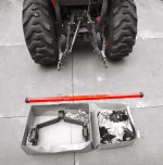
Photo #1 Components - Large box on the left contains the Toolbar gripping component, which mounts on Category 1 Three Point Hitch. Smaller box on right contains 'Danish' S-Tines, S-tine brackets, which attach S-Tines to Tool Bar, 9" Sweeps, nuts and bolts. (I was short two lock washers.) Both boxes of components came from Woodward Crossings.
Toolbar is 2" X 2" X 1/4" wall square steel tubing, available in almost any length from a steel supplier or welding shop. The max length Toolbar which will ship UPS at standard rate is 48". I wanted 70", which Woodward Crossing could have supplied but with a UPS shipping surcharge. I decided to buy my Toolbar locally. I paid $32 for the 70" piece of raw steel. I had it powder-coated Kubota orange, by a powder coating specialty shop.
2" X 2" rubber caps were purchased on eBay, pipe clamps from Ace Hardware. Caps are to exclude bees and snakes from the Toolbar.
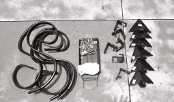
Photo #2 Components laid out on driveway.
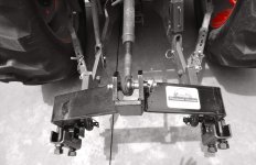
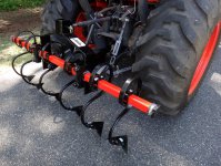
Photo #3 Mount Toolbar Grip on Three Point Hitch, tighten 3-Pt. stabilizers so Grip will not move away from you. Right and left draw pins are turned IN, probably to save shipping space. This seems to be fine for my Three Point so I left it alone. I may turn draw pins OUT in the future. No Top Link pin nor three lynch pins provided.
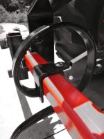
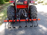
Photo #4 Lay out sweeps to provide rough idea of where to position S-tines. The widest sweeps available for S-tines are 9". I suppose this is to prevent draft force acting on sweeps from bending/deforming S-tines.
Next insert Toolbar in Grip. Tolerances are tight. Lubricate inside brackets to aid insertion and prevent rust. I used spray Lithium grease. The powder-coated orange Toolbar was pretty difficult to insert. I had to separate the two-part brackets, insert the Toolbar, seat the powder-coated Toolbar with a soft blow mallet, then assemble the brackets. Nuts are an odd size, maybe 1-3/8" (or 35mm) so I torqued down nuts lightly with a 12" Crescent wrench.
(Grip may be imported from Italy and therefore nuts may be 35mm metric. S-tines and sweeps are marked MADE IN ITALY.)
Lubricate inside of S-tine brackets to discourage seizing to Toolbar. Set S-tine brackets on Toolbar at appropriate intervals.
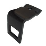
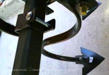
Photo #5-#6-#7 Large window in bracket faces to rear, square hole to accept Carriage bolt goes up, MADE IN ITALY will face up on Toolbar. Thread S-tine around Toolbar and through bracket window, S-tine will hang on bracket. Line up round hole on S-tine below square hold on bracket and insert one long carriage bolt, apply flat washer, then lock washer, nut and snug with 11/16" (18mm) DEEP socket and 20" Breaker Bar or wrench. If you feel like you need three hands, bracket is not oriented properly. LOOK AT PHOTO #5 CLOSELY.
I apply anti-seize grease to bolts. Adjust S-tines along Toolbar. Attach sweeps; elliptical head bolt only, no washers. Make sure elliptical bolt head is correctly seated, flat, before tightening nuts.
Look at sweeps. You want a gap between each sweep. Gaps between my sweeps vary from 3" to 4". You do not want sweeps to have potential to touch.
Tighten all nuts and bolts. They will loosen with use. After third or fourth tightening everything should settle in and the unions should remain tight.
Push on rubber end caps, apply pipe clamps to secure caps to Toolbar.
I paid $330.10 plus freight:
1 3-Pt hitch Toolbar Grip
6 sweeps
6 clamps
6 elliptical head bolts + nuts
6 S-tines
Toolbar purchased locally @ $27.00
WOODWARD CROSSINGS LINK: https://dl.dropboxusercontent.com/u...ld Your Own 3 Pt. Hitch Toolbar System wo.pdf
I am sorry the photos are a little fuzzy. My camera slipped out of the AUTO mode without me noticing, given the extremely bright sunlight today.
Photo #1 Components - Large box on the left contains the Toolbar gripping component, which mounts on Category 1 Three Point Hitch. Smaller box on right contains 'Danish' S-Tines, S-tine brackets, which attach S-Tines to Tool Bar, 9" Sweeps, nuts and bolts. (I was short two lock washers.) Both boxes of components came from Woodward Crossings.
Toolbar is 2" X 2" X 1/4" wall square steel tubing, available in almost any length from a steel supplier or welding shop. The max length Toolbar which will ship UPS at standard rate is 48". I wanted 70", which Woodward Crossing could have supplied but with a UPS shipping surcharge. I decided to buy my Toolbar locally. I paid $32 for the 70" piece of raw steel. I had it powder-coated Kubota orange, by a powder coating specialty shop.
2" X 2" rubber caps were purchased on eBay, pipe clamps from Ace Hardware. Caps are to exclude bees and snakes from the Toolbar.
Photo #2 Components laid out on driveway.
Photo #3 Mount Toolbar Grip on Three Point Hitch, tighten 3-Pt. stabilizers so Grip will not move away from you. Right and left draw pins are turned IN, probably to save shipping space. This seems to be fine for my Three Point so I left it alone. I may turn draw pins OUT in the future. No Top Link pin nor three lynch pins provided.
Photo #4 Lay out sweeps to provide rough idea of where to position S-tines. The widest sweeps available for S-tines are 9". I suppose this is to prevent draft force acting on sweeps from bending/deforming S-tines.
Next insert Toolbar in Grip. Tolerances are tight. Lubricate inside brackets to aid insertion and prevent rust. I used spray Lithium grease. The powder-coated orange Toolbar was pretty difficult to insert. I had to separate the two-part brackets, insert the Toolbar, seat the powder-coated Toolbar with a soft blow mallet, then assemble the brackets. Nuts are an odd size, maybe 1-3/8" (or 35mm) so I torqued down nuts lightly with a 12" Crescent wrench.
(Grip may be imported from Italy and therefore nuts may be 35mm metric. S-tines and sweeps are marked MADE IN ITALY.)
Lubricate inside of S-tine brackets to discourage seizing to Toolbar. Set S-tine brackets on Toolbar at appropriate intervals.
Photo #5-#6-#7 Large window in bracket faces to rear, square hole to accept Carriage bolt goes up, MADE IN ITALY will face up on Toolbar. Thread S-tine around Toolbar and through bracket window, S-tine will hang on bracket. Line up round hole on S-tine below square hold on bracket and insert one long carriage bolt, apply flat washer, then lock washer, nut and snug with 11/16" (18mm) DEEP socket and 20" Breaker Bar or wrench. If you feel like you need three hands, bracket is not oriented properly. LOOK AT PHOTO #5 CLOSELY.
I apply anti-seize grease to bolts. Adjust S-tines along Toolbar. Attach sweeps; elliptical head bolt only, no washers. Make sure elliptical bolt head is correctly seated, flat, before tightening nuts.
Look at sweeps. You want a gap between each sweep. Gaps between my sweeps vary from 3" to 4". You do not want sweeps to have potential to touch.
Tighten all nuts and bolts. They will loosen with use. After third or fourth tightening everything should settle in and the unions should remain tight.
Push on rubber end caps, apply pipe clamps to secure caps to Toolbar.
I paid $330.10 plus freight:
1 3-Pt hitch Toolbar Grip
6 sweeps
6 clamps
6 elliptical head bolts + nuts
6 S-tines
Toolbar purchased locally @ $27.00
WOODWARD CROSSINGS LINK: https://dl.dropboxusercontent.com/u...ld Your Own 3 Pt. Hitch Toolbar System wo.pdf
Attachments
-
 DSC00386.jpg497.4 KB · Views: 298
 -
 DSC00389.jpg523.6 KB · Views: 218
 -
 DSC00388.jpg598.8 KB · Views: 244
 -
 DSC00391.jpg565.5 KB · Views: 173
 -
 DSC00392.jpg548.6 KB · Views: 223
 -
 DSC00396.jpg1,010 KB · Views: 452
 -
 DSC00395.jpg1 MB · Views: 363
 -
 CLAMP.jpg22.5 KB · Views: 177
 -
 Unknown.jpeg27.3 KB · Views: 172
Last edited: